
DIY: electric water pump install w/ pictures
 01-01-2009, 01:34 PM
#1
5th Gear Member
Thread Starter
Join Date: Aug 2007
Location: Lakeland/Mulberry FL
Posts: 2,263
Easy , less than 2 hours.
Parts:
WP346 electric water pump
WIK 346 relay kit
060990 napa belt (if you have under drive pullies already)99 inchs long
Antifreze
Tools:
10mm socket
13mm socket
14mm socket
wire cutters
custom hex head (I made one)******6MM hex head ball end socket******get it from sears

Out of the box in all its glory!
Start with removing your air intake and fans if you need too, I already made alot of room for the upcoming turbo so I dont have any fans to remove at this time.
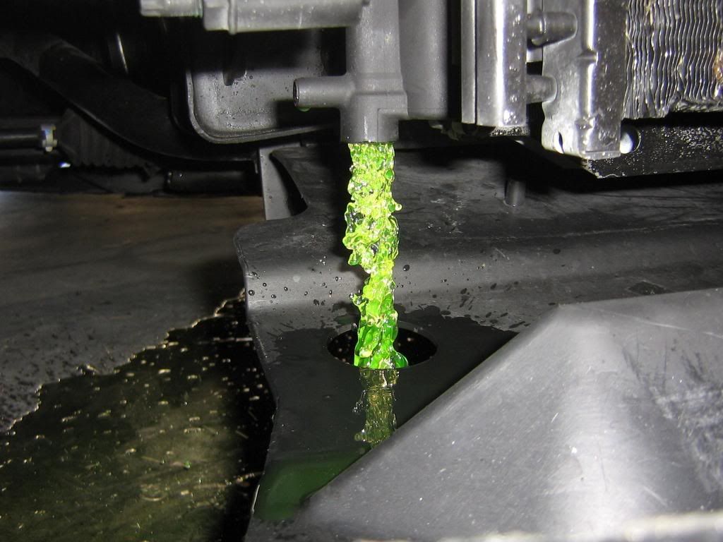
Drain the radiator, I removed the plug completly to let it drain quicker. I used an adjustable wrench to loosen the plug, it loosens very easy.
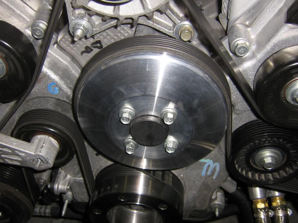
Loosen the (4) 10mm bolts holding the water pump pulley on. You can hold the pulley by hand if you need to, the bolts are torqued at only 18 ft lbs. Do not remove the bolts yet.
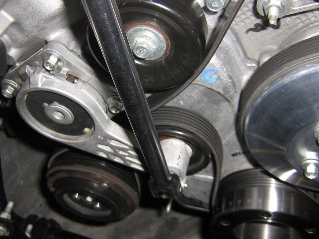
1/2 beaker bar on the tensioner. Just push it towards the driver side and the belt will come right off.
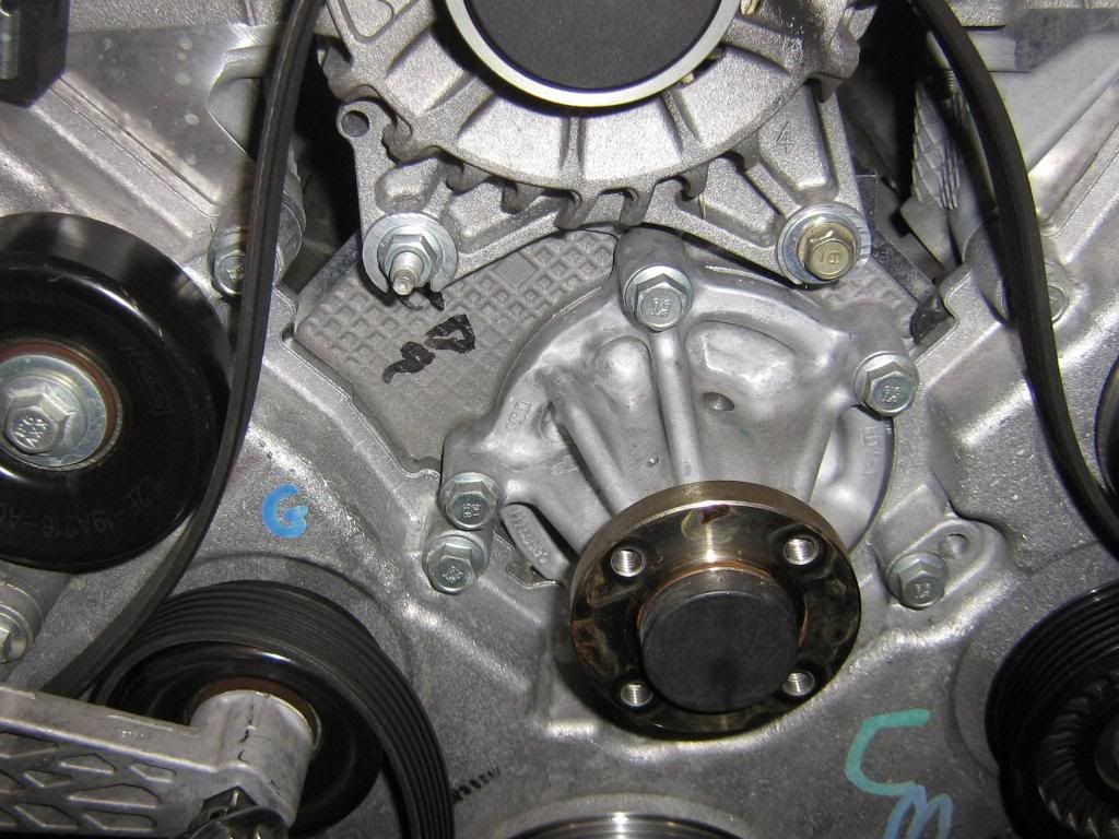
Remove the 4 bolts and the pulley falls off in your hands. then remove the 4 bolts holding the pump in,they are 13mm bolts. once those 4 bolts are removed, you can just pull the pump out.
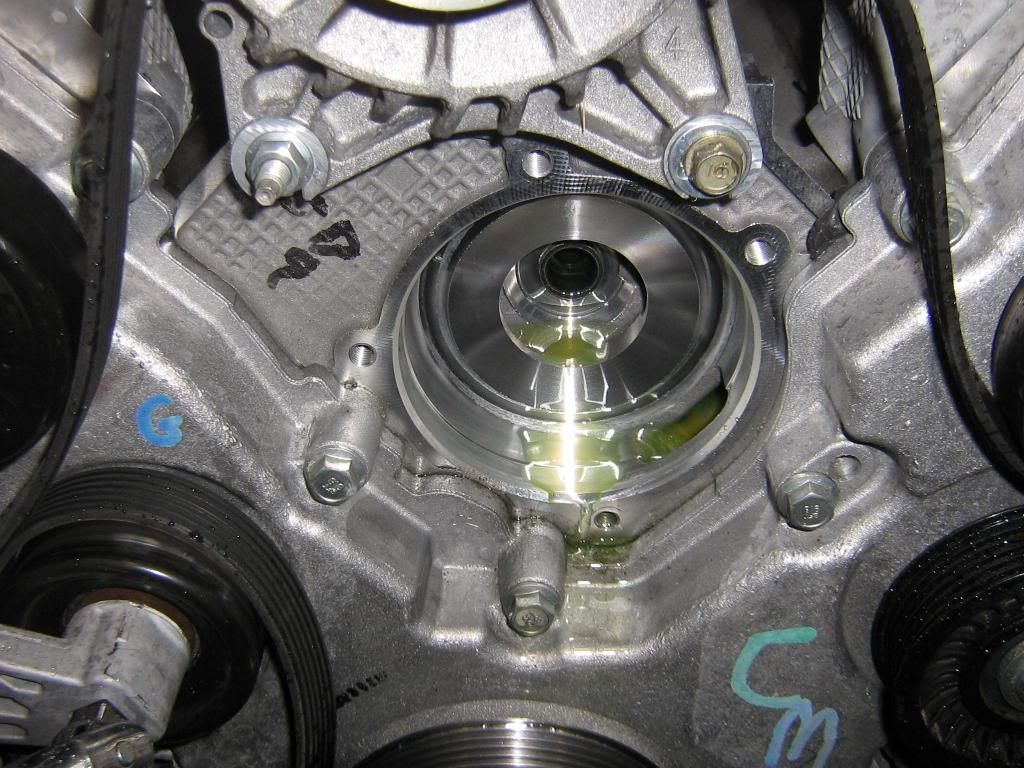
Heres what it looks like, a ton of water still came out even though i drained the fluids. No big deal.
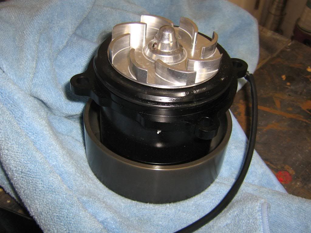
New pump comes with grease on the o-ring already.
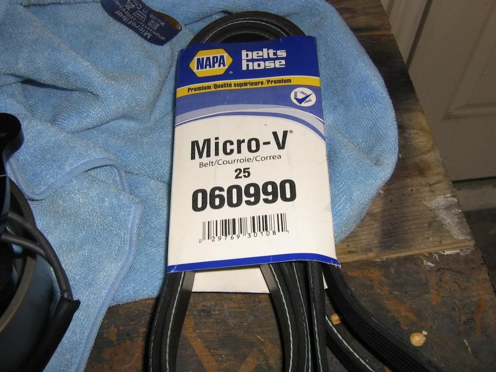
new belt from napa. you wont need a new belt if you dont have under drive pullies. i installed under drive pullies last weekend so i needed the new belt, it is only 99 inches long compared to the stocker at 101.5 inches long.
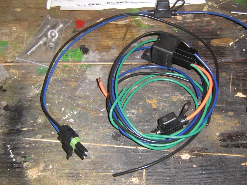
Wiring kit from Meziere, its basicly a relay with wire, if you wanted to shave $20 off this project you could just get it from the auto parts store for $10.
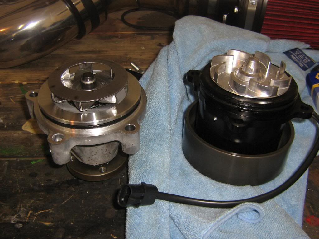
NEW vs OLD
new pump just slides right in, wiglle it a little so you dont chomp the o-ring. Its very nice not to have to deal with sealant and that the o-ring is there to make the seal.
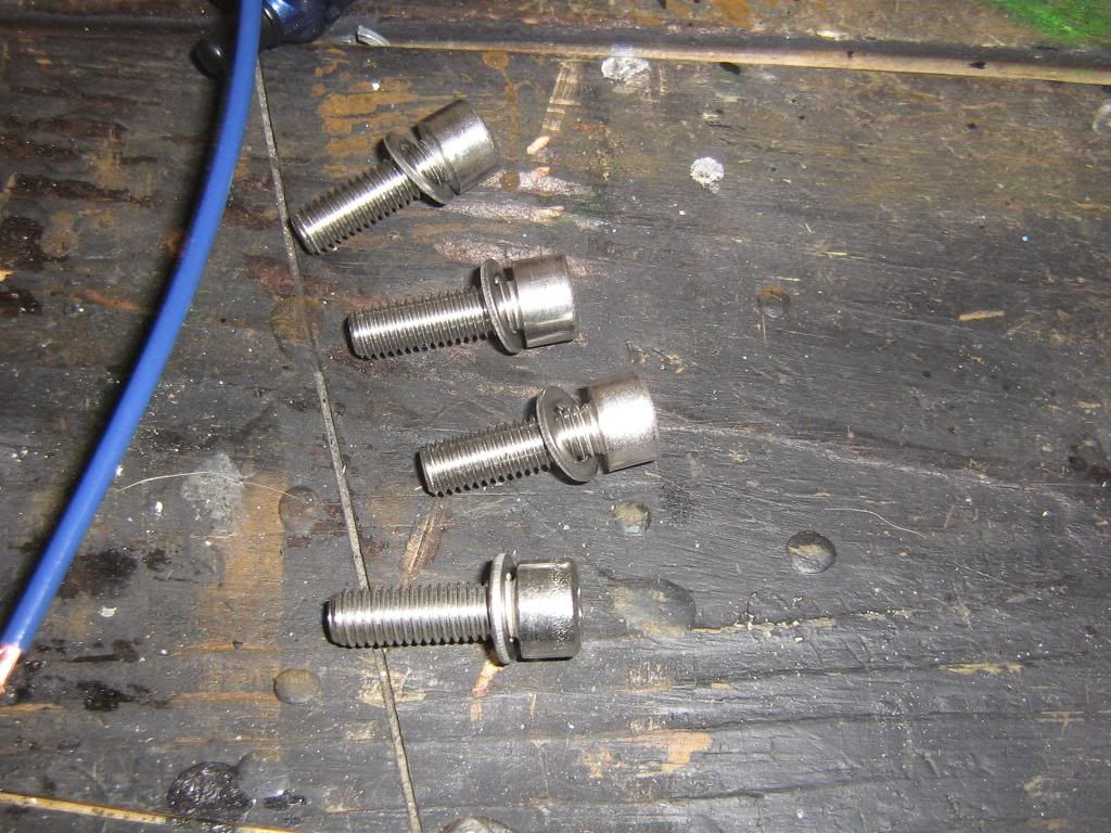
the pump comes with (4) 6mm hex head bolts and 4 washers,all stainless
I used a dab of locktite on each new bolt.
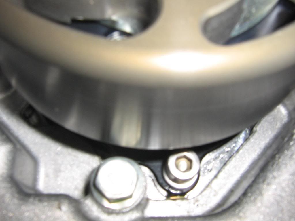
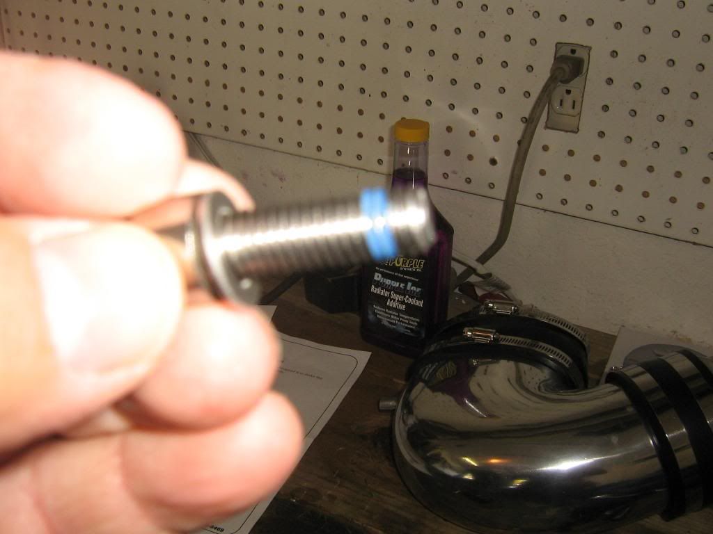
First i got them all finger tight, in this pic you can see how the bolts are behind the pulley, so you cant get a wrench on them or a rachet or even a regular hex head allen wrench. So i made one that woukld work for me.
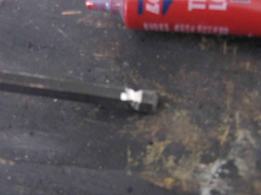
I used a grinder and rounded off the tip, then made a groove around the allen wrench to it would allow the allen wrench to pivot inside the bolt as i turned it. the instructions dont mention any thing of this issue and i dont see how else you could tighten them unless you used something like what i had to make.
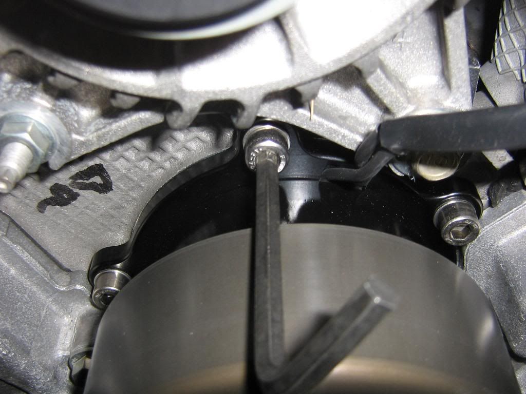
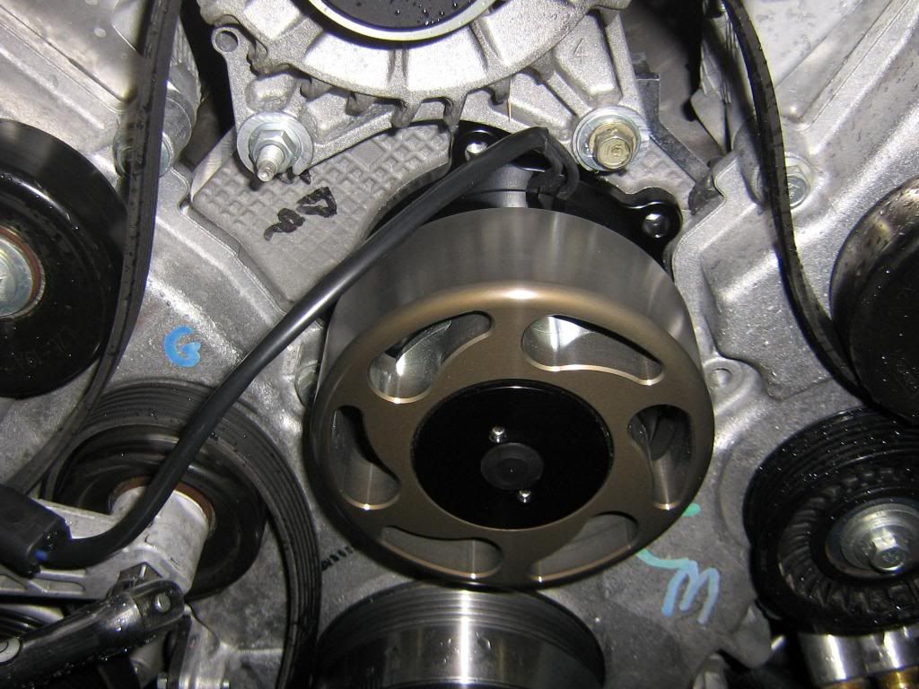
here you can see the angle of the allen wrench once its in the hole. Just tighten all the bolts equally until they are good and tight, the bolts are just there to hold the pump in place and the o-ring does all the work for sealing it.
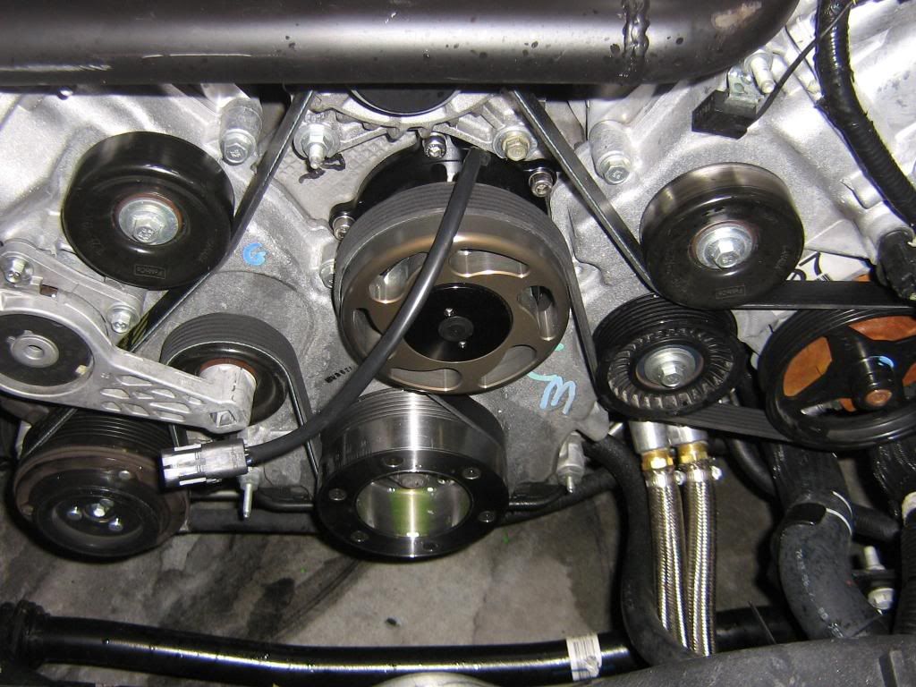
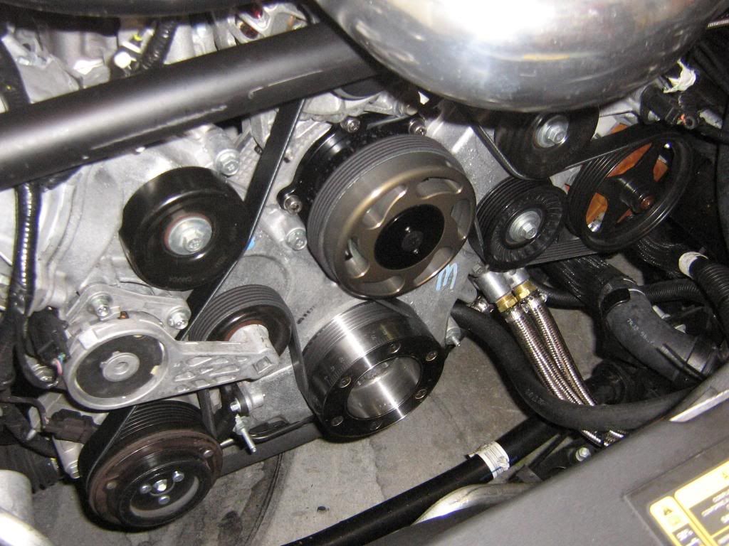
Nice and purdy
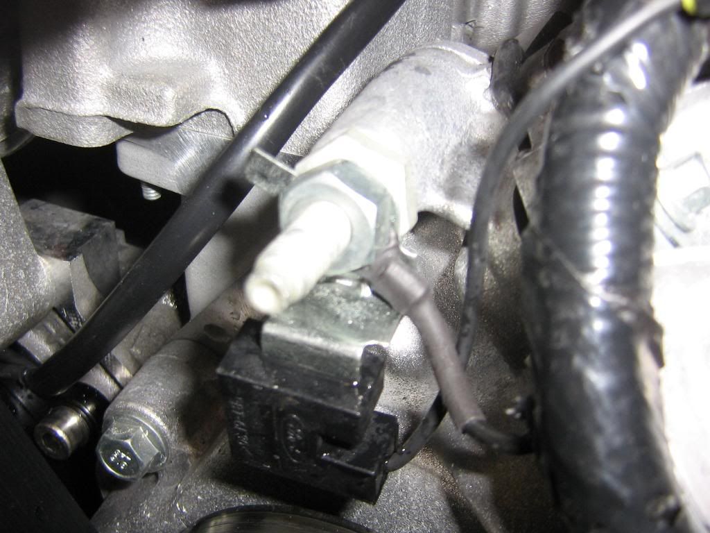
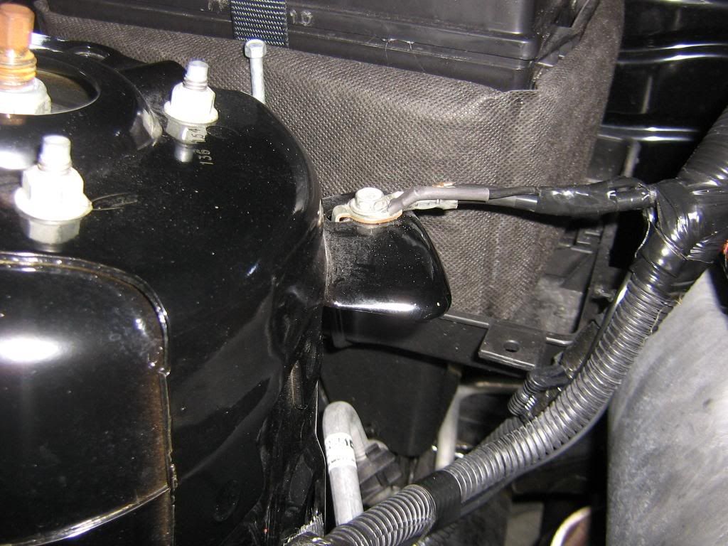
To start the wiring i ran the pump wires to the driver side valve cover, you must ground the black wire from the pump to a ground on the chassis. I used the bolt on the front of the head and heatshrinked it,looks factory.
Parts:
WP346 electric water pump
WIK 346 relay kit
060990 napa belt (if you have under drive pullies already)99 inchs long
Antifreze
Tools:
10mm socket
13mm socket
14mm socket
wire cutters
custom hex head (I made one)******6MM hex head ball end socket******get it from sears
Out of the box in all its glory!
Start with removing your air intake and fans if you need too, I already made alot of room for the upcoming turbo so I dont have any fans to remove at this time.
Drain the radiator, I removed the plug completly to let it drain quicker. I used an adjustable wrench to loosen the plug, it loosens very easy.
Loosen the (4) 10mm bolts holding the water pump pulley on. You can hold the pulley by hand if you need to, the bolts are torqued at only 18 ft lbs. Do not remove the bolts yet.
1/2 beaker bar on the tensioner. Just push it towards the driver side and the belt will come right off.
Remove the 4 bolts and the pulley falls off in your hands. then remove the 4 bolts holding the pump in,they are 13mm bolts. once those 4 bolts are removed, you can just pull the pump out.
Heres what it looks like, a ton of water still came out even though i drained the fluids. No big deal.
New pump comes with grease on the o-ring already.
new belt from napa. you wont need a new belt if you dont have under drive pullies. i installed under drive pullies last weekend so i needed the new belt, it is only 99 inches long compared to the stocker at 101.5 inches long.
Wiring kit from Meziere, its basicly a relay with wire, if you wanted to shave $20 off this project you could just get it from the auto parts store for $10.
NEW vs OLD
new pump just slides right in, wiglle it a little so you dont chomp the o-ring. Its very nice not to have to deal with sealant and that the o-ring is there to make the seal.
the pump comes with (4) 6mm hex head bolts and 4 washers,all stainless
I used a dab of locktite on each new bolt.
First i got them all finger tight, in this pic you can see how the bolts are behind the pulley, so you cant get a wrench on them or a rachet or even a regular hex head allen wrench. So i made one that woukld work for me.
I used a grinder and rounded off the tip, then made a groove around the allen wrench to it would allow the allen wrench to pivot inside the bolt as i turned it. the instructions dont mention any thing of this issue and i dont see how else you could tighten them unless you used something like what i had to make.
here you can see the angle of the allen wrench once its in the hole. Just tighten all the bolts equally until they are good and tight, the bolts are just there to hold the pump in place and the o-ring does all the work for sealing it.
Nice and purdy
To start the wiring i ran the pump wires to the driver side valve cover, you must ground the black wire from the pump to a ground on the chassis. I used the bolt on the front of the head and heatshrinked it,looks factory.
Last edited by one eyed willy; 05-15-2010 at 01:43 PM.
 01-01-2009, 01:35 PM
#2
5th Gear Member
Thread Starter
Join Date: Aug 2007
Location: Lakeland/Mulberry FL
Posts: 2,263
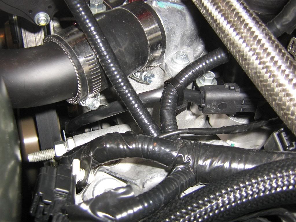
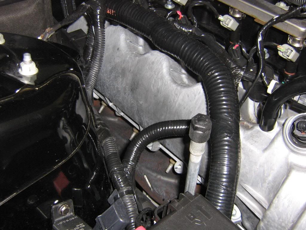
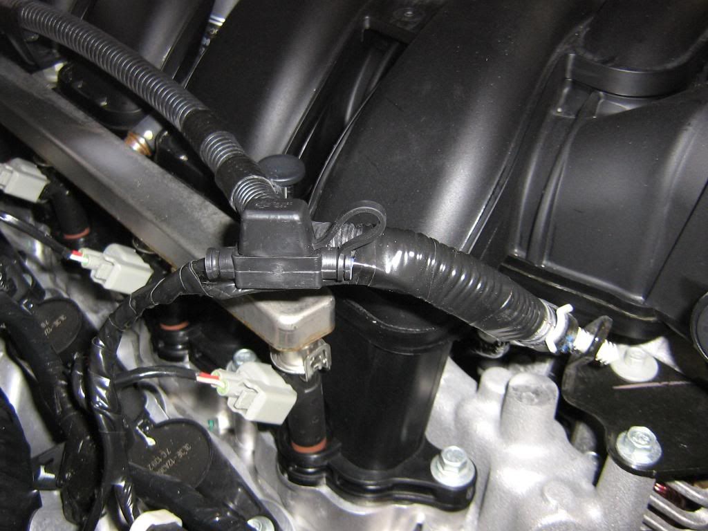
here you can see how i routed the wire from the pump.I then routed the blue wire from the pump under the intake, and behind the alternator using a coat hanger to push it over, this way the wire was all hidden and not seen.
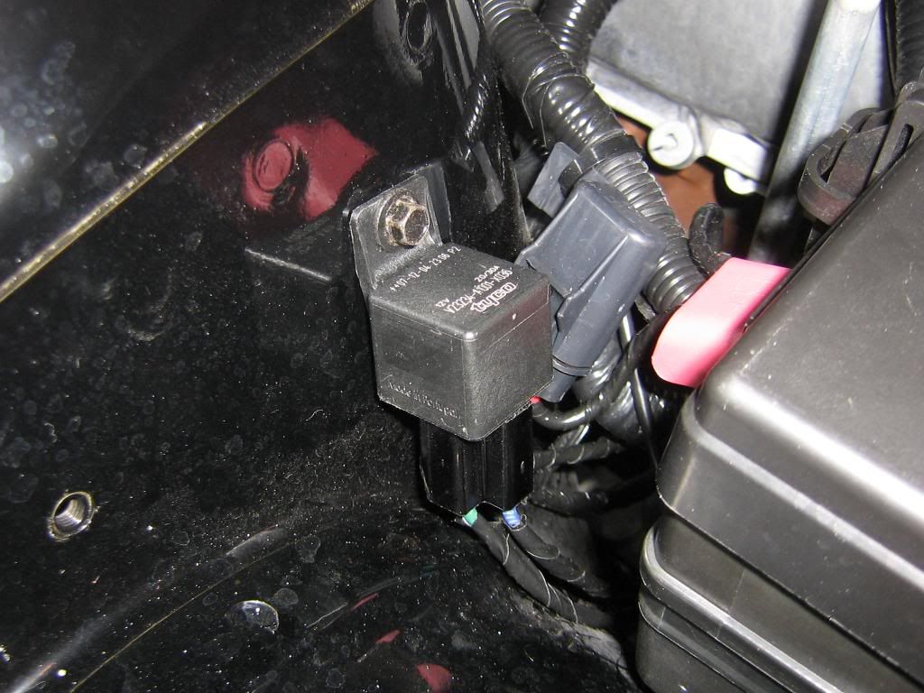
I installed the relay just behind the fuse box using the hole that was already there.The orange wire went to the battery connection in the fuse box.
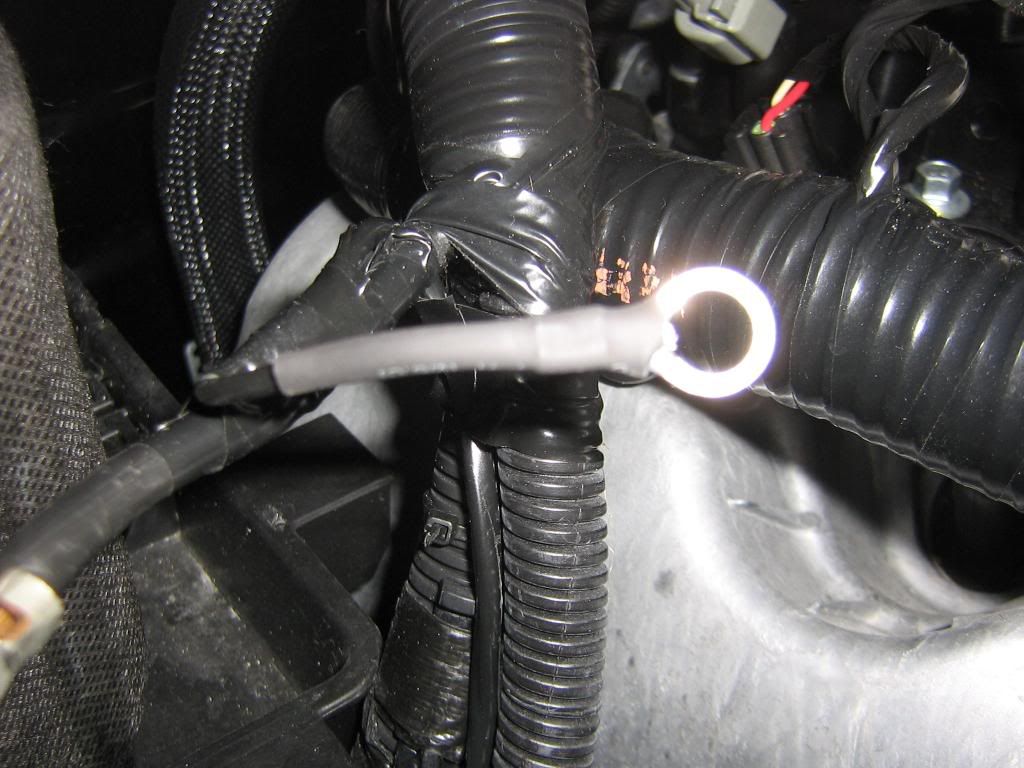
I ran the black ground wire from the relay up to where the battery grounds. Heatshrinked.
Like factory.
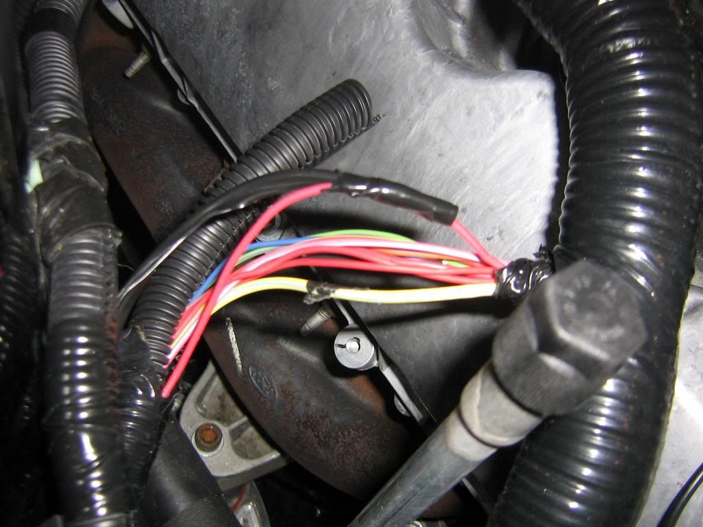
next i ran the green wire from the relay to a red wire in the factory loom that only has 12v with the key on, this wire is not used for anything other than to trip the relay that will send 12v to the pump.
All put back and taped up like factory.
Water pump fuse.
I put some ICE in when filling the antifreeze back up.
Engine running.
Over all this was a very simple install and took less than 2 hours, i spent most my time looking for that red wire to power the relay.
AFTER DRIVING: temps are 10 degrees less when just cruising around, and when i get on it the temps go up breifly but come back down very quick. i also did notice a boost in th gas pedal. I feel it more now than when i did the under drive pullies. Plus when im at the track i can just turn the key now to cool the engine and let the pump cool the motor down.
I plan to reseach a way to tell me if the pump is pulling a load, one downfall to these pumps are when they die, your screwed and dont know it unless your watching the temp gauge. When i had my camero there were guys that used some LEDS and resitors, the LED would come on when the pump stop drawing a load,so it would tell you when the pump died before your motor died. I plan to do this very soon.
I wont be doing the thermostat until i do the cmdp, should be next weekend i hope.
Last edited by one eyed willy; 02-10-2009 at 07:32 PM.
01-01-2009, 04:07 PM
#4
5th Gear Member
Join Date: Apr 2008
Location: Memphis
Posts: 2,377
Great write up man. Forgive my ignorance but how does the thermostat work in relation to the pump? Or does it at all? And I've heard of people installing volt meters to keep an eye on the load it's drawing but that LED set up sounds pretty slick!
01-01-2009, 05:06 PM
#6
5th Gear Member
Thread Starter
Join Date: Aug 2007
Location: Lakeland/Mulberry FL
Posts: 2,263
no relation to the pump, but on the 07 gt, the thermostat housing is almost underneath the intake. since i will be pulling the intake to do the cmdp im waiting on the thermostat.hopefully my tuner will be here soon so i can do the cmdp.
01-01-2009, 05:08 PM
#7
5th Gear Member
Join Date: Apr 2008
Location: Memphis
Posts: 2,377
 01-01-2009, 05:34 PM
#9
5th Gear Member
Thread Starter
Join Date: Aug 2007
Location: Lakeland/Mulberry FL
Posts: 2,263
heres a wiring diagram i lan to use to make me a indicator incase the pump fials on me, the led should light up when ever the pump fails,ill test it on the bench first.
http://www.akmcables.com/mezinst2.jpg
01-01-2009, 06:40 PM
#10
6th Gear Member
Join Date: Nov 2007
Location: Montaner
Posts: 6,193
Nice writeup. Without the grinder it's going to be a bit more than 2 hours and perhaps not "easy".
If the pump fails and the car overheats you should eventually get a check engine and it'll go into limp mode before permanent damage occurs. Or so I've heard.
If the pump fails and the car overheats you should eventually get a check engine and it'll go into limp mode before permanent damage occurs. Or so I've heard.