
Kenne Bell Boost-A-Pump install (w/pics)
 05-05-2008, 02:33 PM
#1
2nd Gear Member
Thread Starter
Join Date: Jun 2006
Location:
Posts: 415
This KB BAP is part of my Vortech S/C kit from Brenspeed.
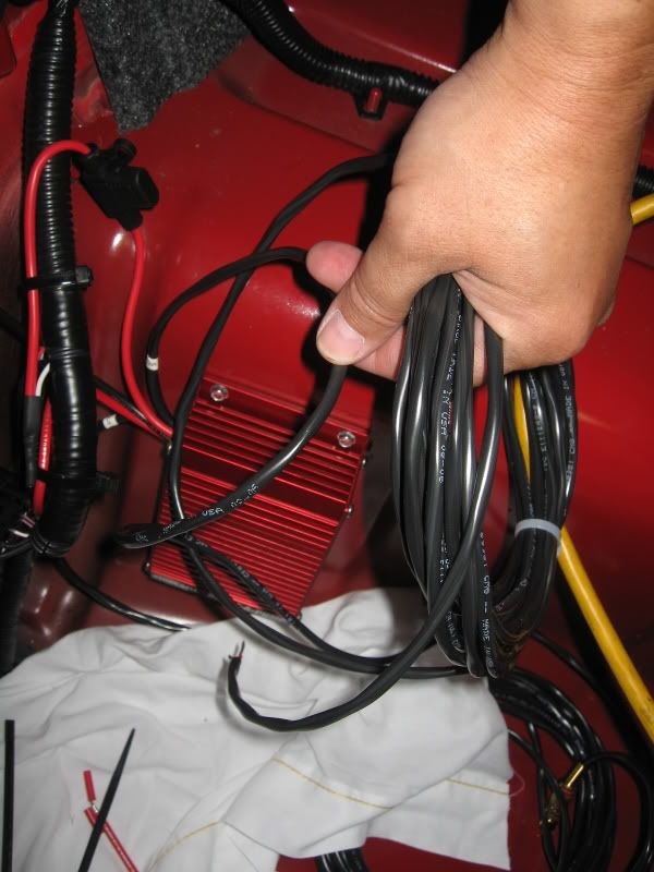
There are only 5 wires coming out of the BAP;
Black Ground
Red fused
Red non-fused
Long sheathed RCA plugged wire for dial control box
Long sheathed wires for Boost/Vacuum switch
Only deviation from the KB directions is that the 2 wires that would normally go to the boost activation switch has been bypassed to be ‘always on’. This is per Brenspeed’s recommendations.
Tools required
Wire cutter/stripper/crimper
Soldering iron
Heat shrink tubing
Heat gun (or equilv.)
Electrical tape
Marker pen
Small drill and socket set
Phillips screwdriver
Tie-straps
Install time: 1-2 hours
Disconnect the Negative lead off the battery
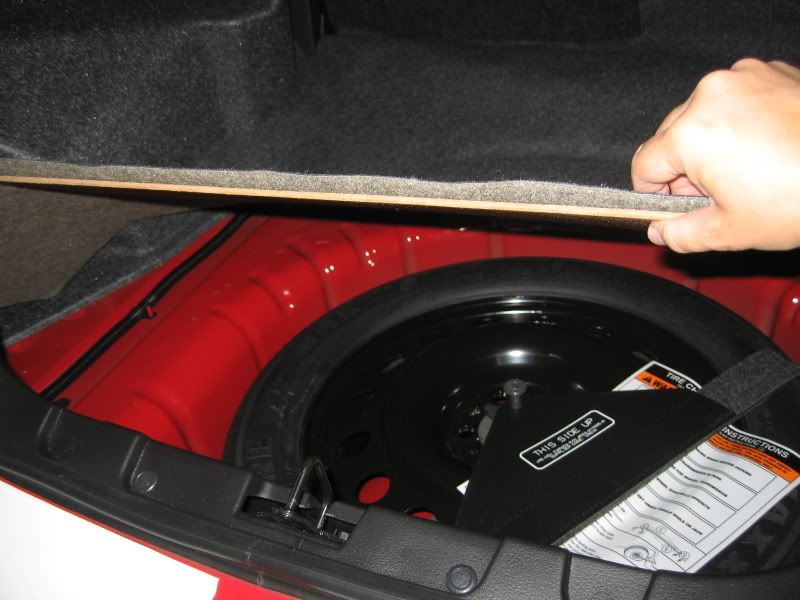
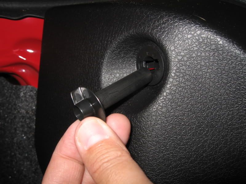
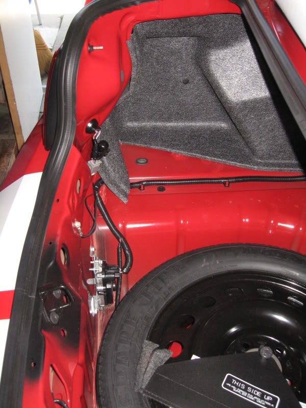
Remove rear panel in trunk; 4 push-pins (can be pulled with fingers) and 2 screw-in fasteners. Also remove carpet base board and set aside.
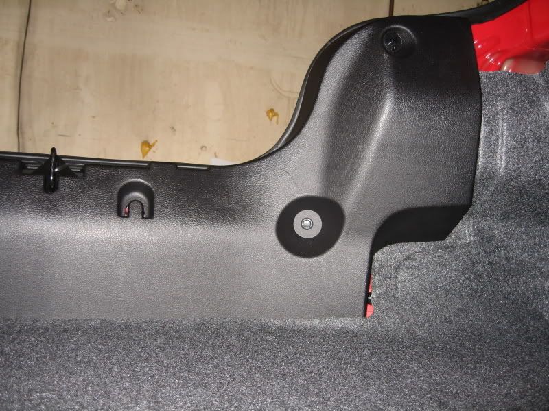


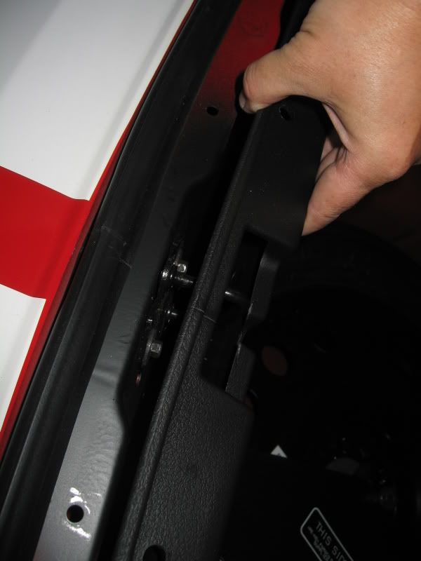
Pop the rear panel over the center latch and remove from car.
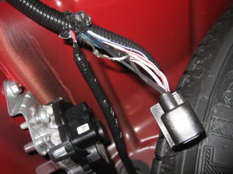
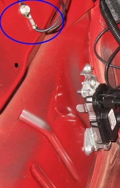
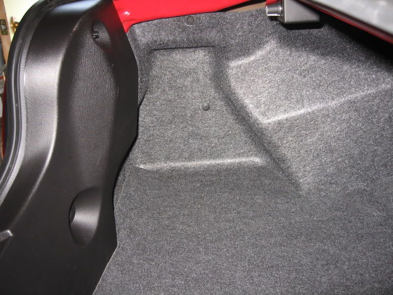
Baseline pictures showing the FPDM (Fuel Pump Driver Module) against the back wall in the spare tire stowage compartment.

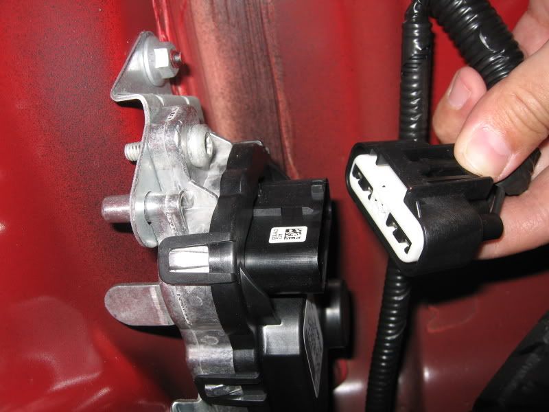
Depress the release tab of the FPDM connector and remove plug
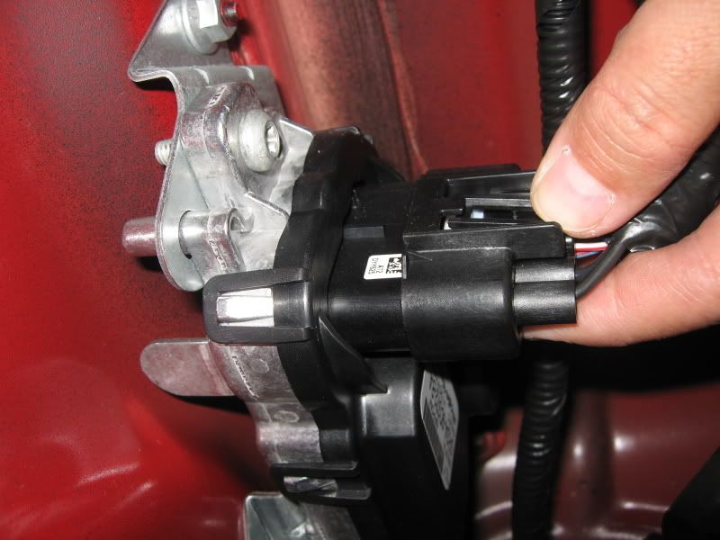
Remove electrical tape off conduit to expose the wires up to the first wire junction
Note: Exposed wire strands were there from the factory. Not sure of its purpose, so I left them as is.
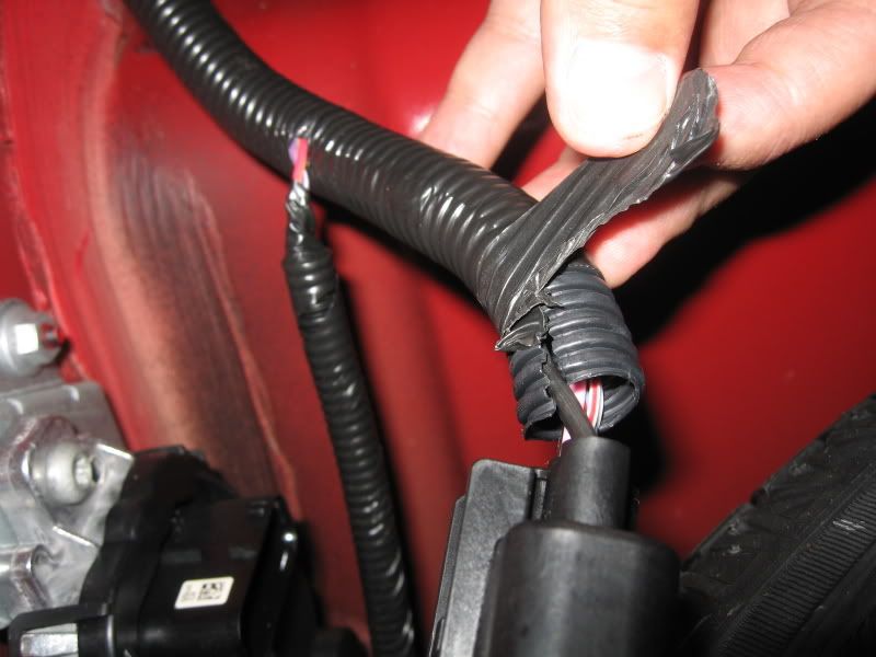
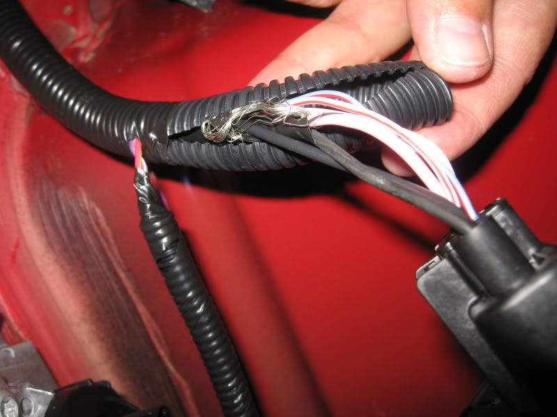
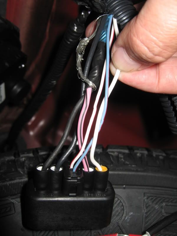
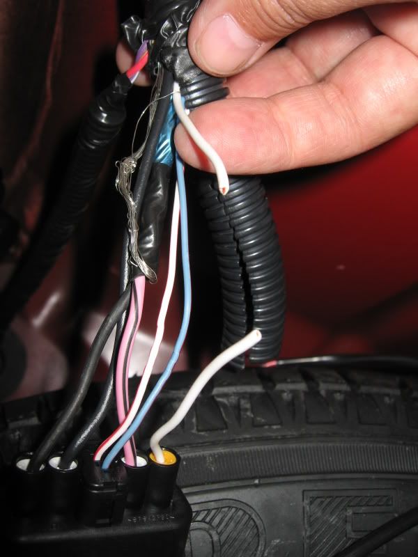
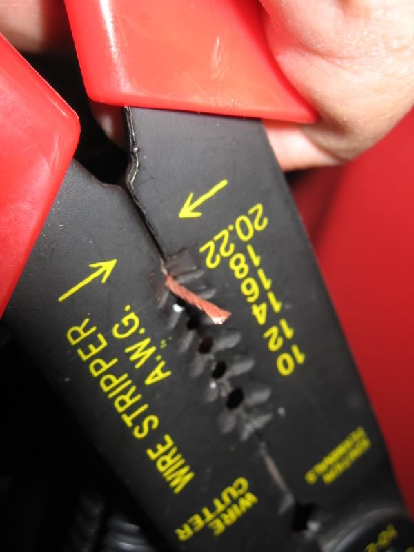
Locate the most outward WHITE wire on the FPDM plug and cut midway, then strip off the insulation off each end (~1/4”)

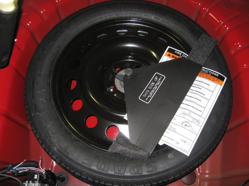
Remove spare tire to allow more working space
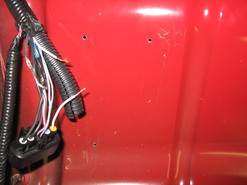
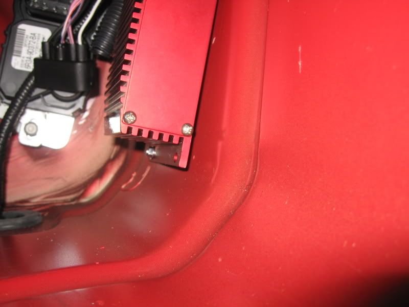
Hand locate the BAP module and mark the upper 2 holes with a market pen.
Note: Module will not lay flat on all 4 corners at this location, so I chose to use the top 2 plus the lower aft hole.

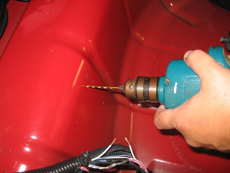
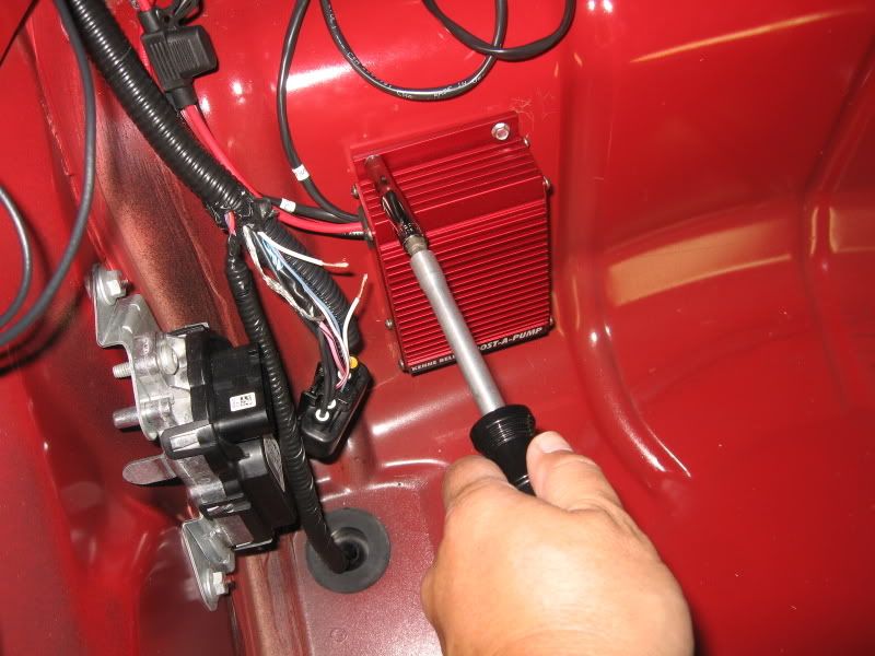
Using a 7/64 drill bit (correct size for the screws in my kit, but double check with your actual included screws), carefully drill were previously marked.
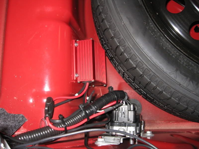
Install BAP module
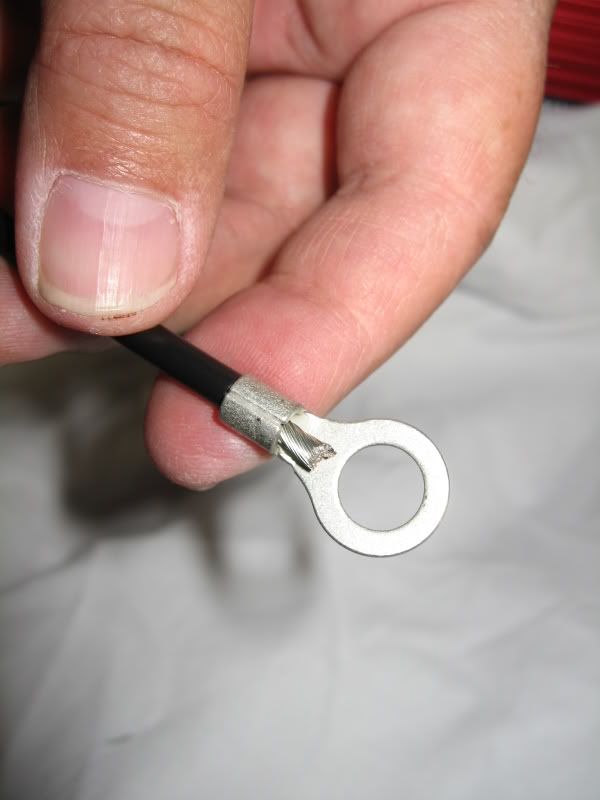
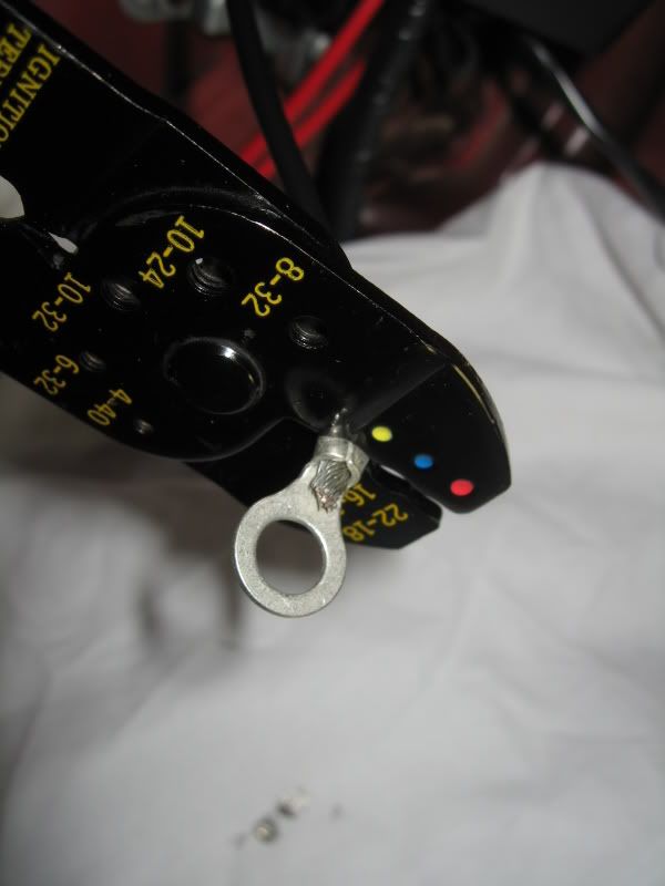
Attach ground terminal on ground wire and crimp. Strongly suggest to follow up with solder.
Attach ground wire to ground as shown.
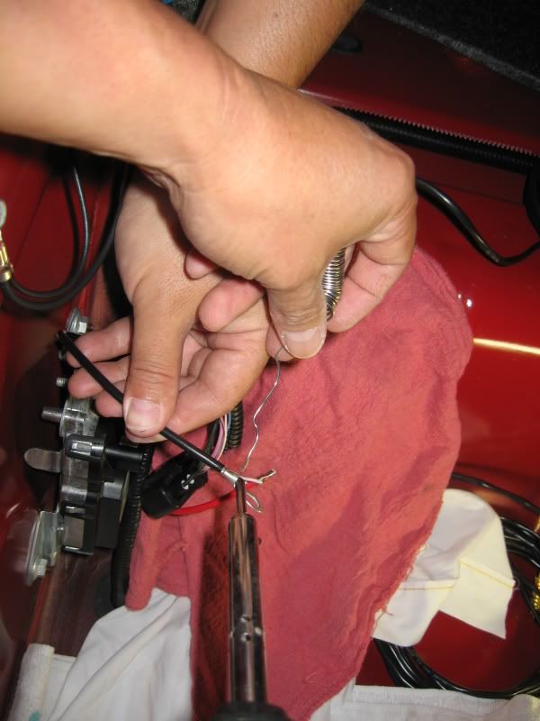
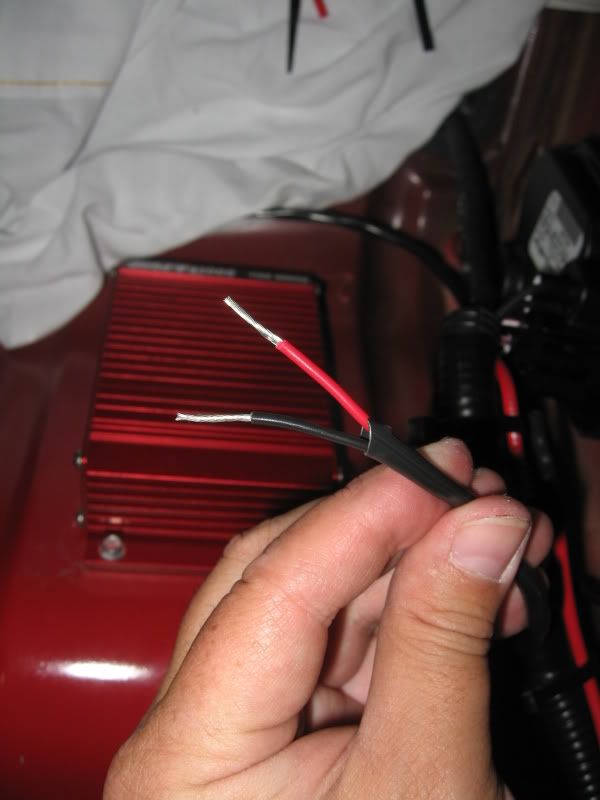
Attach the 2 RED wires off the BAP to the WHITE wires off the FPDM that you cut earlier. Make sure you wire this correctly. After you do, make sure once again.
Solder wires and slip over a shrink tube for added protection.
Note: Use caution when applying heat (ie. Heat gun) to the shrink tubing. Only apply enough heat to shrink the tubing over the wires.
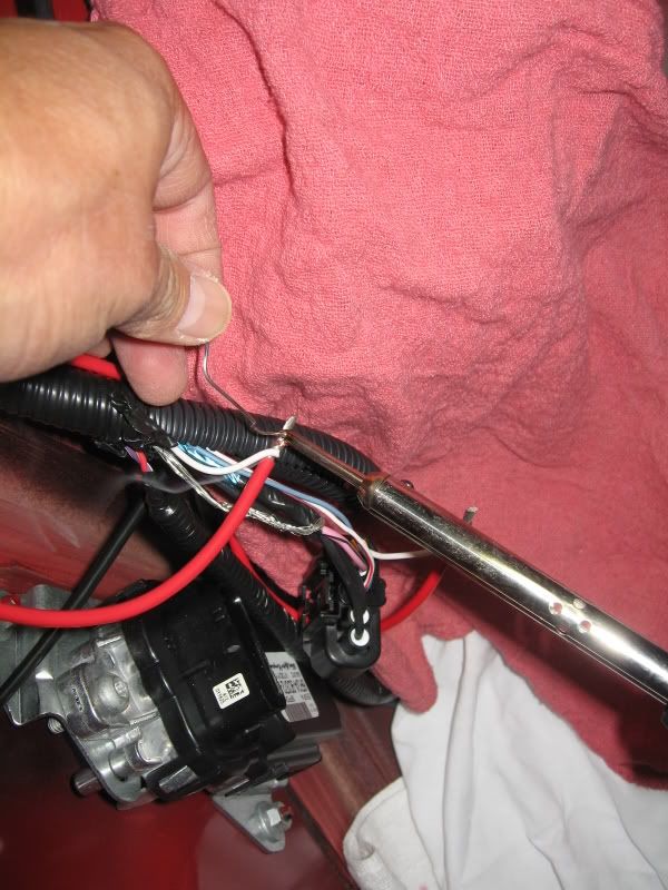

Locate the long sheathed wires for the boost switch. Since Brenspeed instructs to bypass the boost switch, I did not need the extra length. I cut it down in length so it’s near the FPDM wire bundle.
Note: Follow your Tuner’s advice as to whether or not the boost switch will be utilized or not. If you will be using the boost switch, you’ll need to run this wire through the interior (or under the car using the grommet right above the BAP location) into the engine bay to the boost switch. Refer to the included KB instructions (or specific instructions provided by your Tuner) for further instructions on how to hook up the boost switch.
Strip off ~1/4 to 1/2" of insulation, twist together, solder, and heat shrink.
Replace FPDM connector, conduit, apply electrical tape as necessary, and secure loose wires with tie-straps.

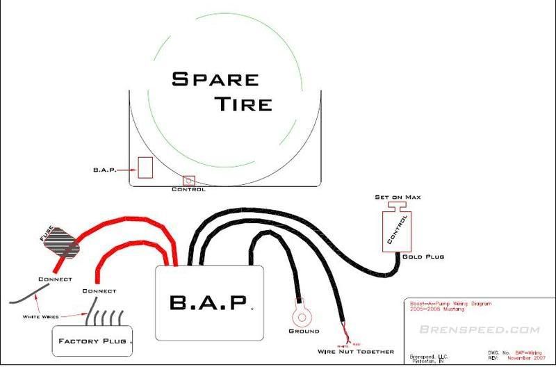
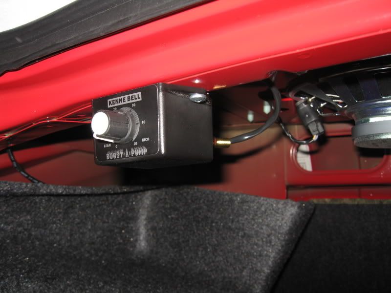
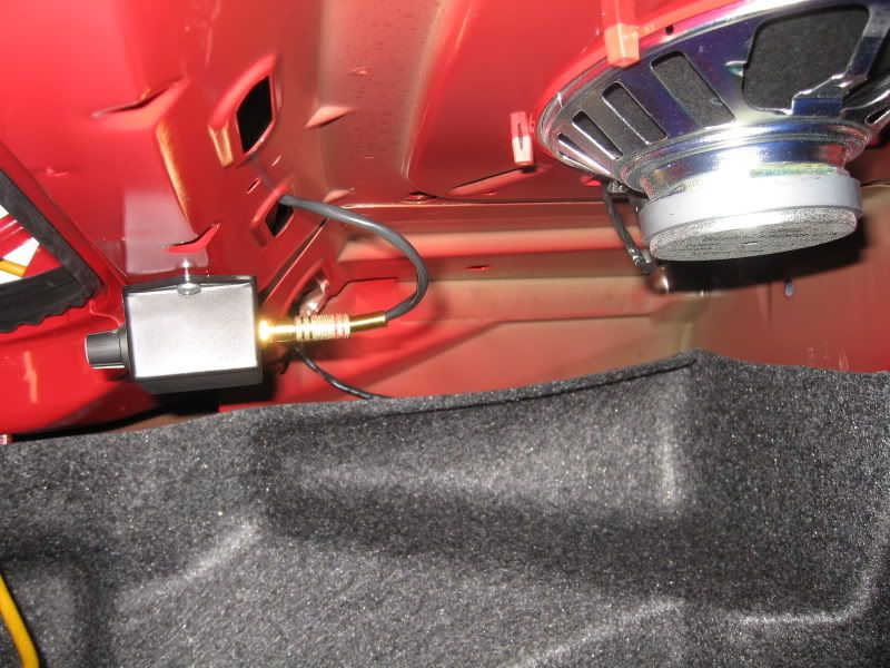
BAP control box
Locate the control box adjacent to the BAP module in the spare tire stowage compartment (per the illustration above) and coil the extra length of wire so it doesn’t interfere with any sharp objects.
I chose to mount the control box under the rear deck of where the speakers are. I did this just for looks as once its set, I will not adjust it again (Max at 50 for Brenspeed application).
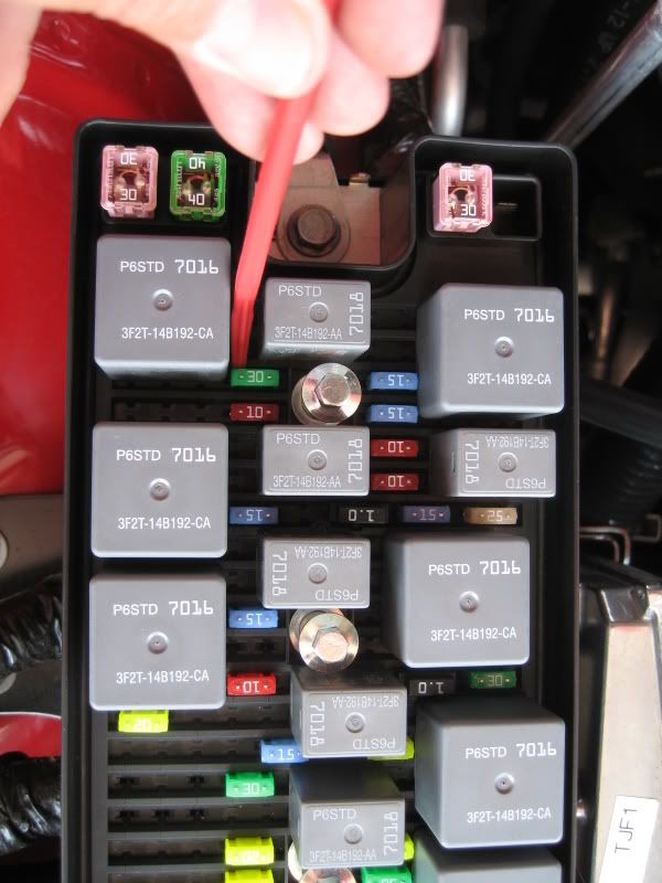
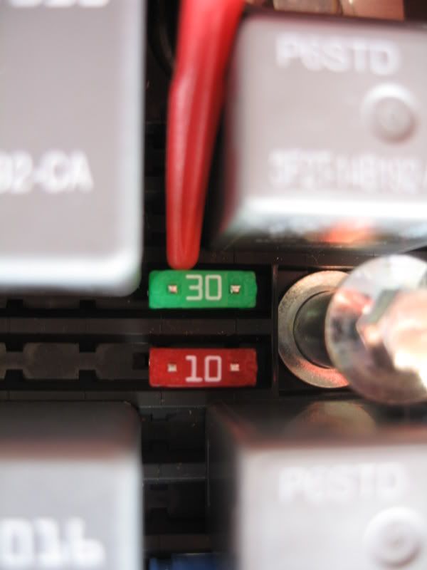
Pop the fuse cover off in the engine bay and replace the factory fuse with the 30 amp fuse provided
Completing installation
Verify everything is connected properly.
Re-connect Negative battery lead.
Turn key to ‘ON’ position.
You should hear a faint electrical buzzing sound coming from the BAP module. It can barely be heard, so a quiet area is a must.
As you turn the dial on the control box (from min to max), the buzzing sound changes in oscillation at the same volume.
Replace spare tire and carpet base board.
Sound operation video
Installation complete!
There are only 5 wires coming out of the BAP;
Black Ground
Red fused
Red non-fused
Long sheathed RCA plugged wire for dial control box
Long sheathed wires for Boost/Vacuum switch
Only deviation from the KB directions is that the 2 wires that would normally go to the boost activation switch has been bypassed to be ‘always on’. This is per Brenspeed’s recommendations.
Tools required
Wire cutter/stripper/crimper
Soldering iron
Heat shrink tubing
Heat gun (or equilv.)
Electrical tape
Marker pen
Small drill and socket set
Phillips screwdriver
Tie-straps
Install time: 1-2 hours
Disconnect the Negative lead off the battery
Remove rear panel in trunk; 4 push-pins (can be pulled with fingers) and 2 screw-in fasteners. Also remove carpet base board and set aside.
Pop the rear panel over the center latch and remove from car.
Baseline pictures showing the FPDM (Fuel Pump Driver Module) against the back wall in the spare tire stowage compartment.
Depress the release tab of the FPDM connector and remove plug
Remove electrical tape off conduit to expose the wires up to the first wire junction
Note: Exposed wire strands were there from the factory. Not sure of its purpose, so I left them as is.
Locate the most outward WHITE wire on the FPDM plug and cut midway, then strip off the insulation off each end (~1/4”)
Remove spare tire to allow more working space
Hand locate the BAP module and mark the upper 2 holes with a market pen.
Note: Module will not lay flat on all 4 corners at this location, so I chose to use the top 2 plus the lower aft hole.
Using a 7/64 drill bit (correct size for the screws in my kit, but double check with your actual included screws), carefully drill were previously marked.
Install BAP module
Attach ground terminal on ground wire and crimp. Strongly suggest to follow up with solder.
Attach ground wire to ground as shown.
Attach the 2 RED wires off the BAP to the WHITE wires off the FPDM that you cut earlier. Make sure you wire this correctly. After you do, make sure once again.
Solder wires and slip over a shrink tube for added protection.
Note: Use caution when applying heat (ie. Heat gun) to the shrink tubing. Only apply enough heat to shrink the tubing over the wires.
Locate the long sheathed wires for the boost switch. Since Brenspeed instructs to bypass the boost switch, I did not need the extra length. I cut it down in length so it’s near the FPDM wire bundle.
Note: Follow your Tuner’s advice as to whether or not the boost switch will be utilized or not. If you will be using the boost switch, you’ll need to run this wire through the interior (or under the car using the grommet right above the BAP location) into the engine bay to the boost switch. Refer to the included KB instructions (or specific instructions provided by your Tuner) for further instructions on how to hook up the boost switch.
Strip off ~1/4 to 1/2" of insulation, twist together, solder, and heat shrink.
Replace FPDM connector, conduit, apply electrical tape as necessary, and secure loose wires with tie-straps.
BAP control box
Locate the control box adjacent to the BAP module in the spare tire stowage compartment (per the illustration above) and coil the extra length of wire so it doesn’t interfere with any sharp objects.
I chose to mount the control box under the rear deck of where the speakers are. I did this just for looks as once its set, I will not adjust it again (Max at 50 for Brenspeed application).
Pop the fuse cover off in the engine bay and replace the factory fuse with the 30 amp fuse provided
Completing installation
Verify everything is connected properly.
Re-connect Negative battery lead.
Turn key to ‘ON’ position.
You should hear a faint electrical buzzing sound coming from the BAP module. It can barely be heard, so a quiet area is a must.
As you turn the dial on the control box (from min to max), the buzzing sound changes in oscillation at the same volume.
Replace spare tire and carpet base board.
Sound operation video
Installation complete!
 05-05-2008, 02:52 PM
#2
2nd Gear Member

Join Date: Jul 2007
Location: Indianapolis, IN
Posts: 468
ah HA! caught you this time, mr. tacobill! You have an extra left hand, which is why you can do these amazing write-ups. your secret is no longer secret! [8D]
03-26-2009, 08:28 AM
#8
4th Gear Member
Join Date: Dec 2008
Location: Texas
Posts: 1,482
09-09-2011, 10:27 AM
#9
2nd Gear Member
Join Date: Apr 2006
Location: WA
Posts: 276
Nice writeup. My only concern would be replacing the stock 15 amp fuel pump fuse with a 30 amp fuse. If there were a problem with the circuit the stock small wires would get fried before the 30 amp fuse kicked in.
12-08-2011, 03:06 AM
#10

Join Date: Dec 2011
Location: anglejel27
Posts: 8
Heat shrink tubing comes in multiple types and this is performed via the process of using a color code.
heat shrink tubing
heat shrink tubing

