
Retro Solutions HID kit Install/Write Up
 01-20-2013, 10:58 PM
#1
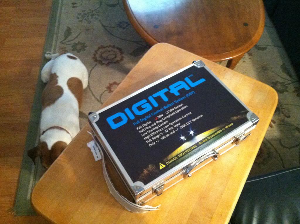
Finally installed my HIDs from Retro Solutions and I'm quite happy with them. Even the 35 Watt is a vast improvement over your stock halogens, and I even have dark smoked housings. Here are the steps I've taken to ensure proper function (though not without some headaches along the way!). I went with the 35 Watt digital system with capped bulbs and slim ballasts. Sorry, but these pictures were taken with an Iphone.
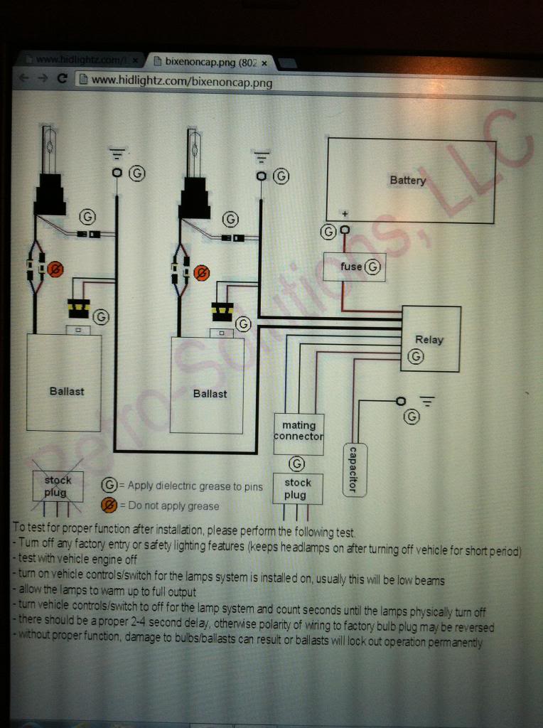
Begin with reviewing the wiring diagram. Notice how the only connections that DO NOT need the provided dielectric grease to be applied are the connections between each ballast and bulb (4 connectors).
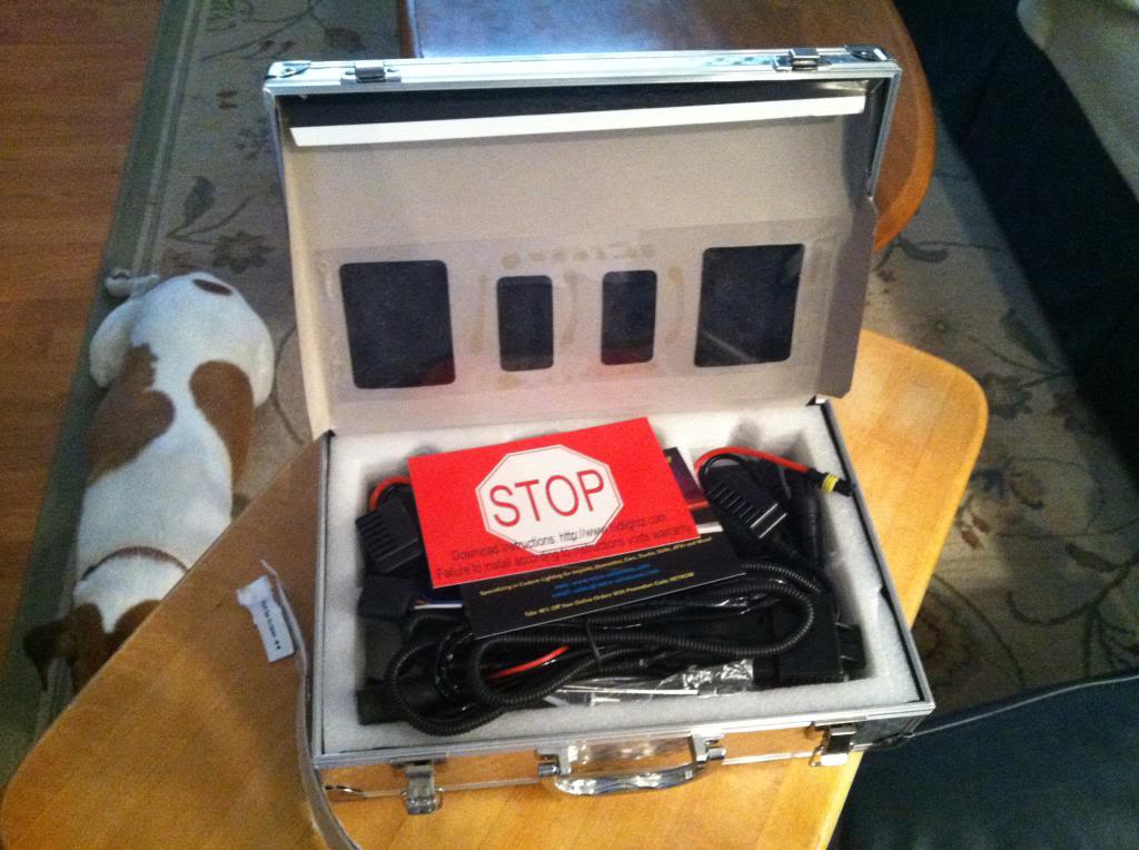
Unboxing: Here is what is provided: 1 relay harness, 2 ballasts and mounting hardware (6 tiny screws to secure plate to balast and 2 bolts/nuts to mount plate to car), 2 bulbs of your chosen intensity, 1 fuse, 1 small bottle of dielectric grease, and 3 small zip ties.
1) Disconnect positive terminal on the battery and ensure proper lighting.
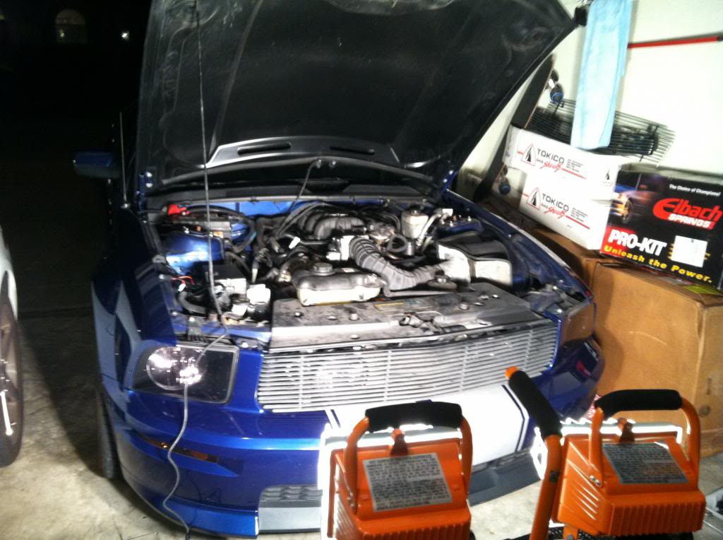
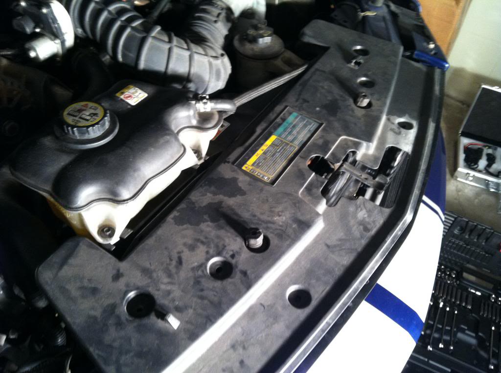
2) Remove radiator cover
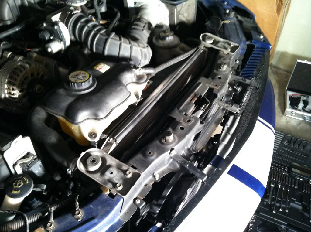
3) Thread the long wire loom along the length of the radiator following the existing electrical wire loom.
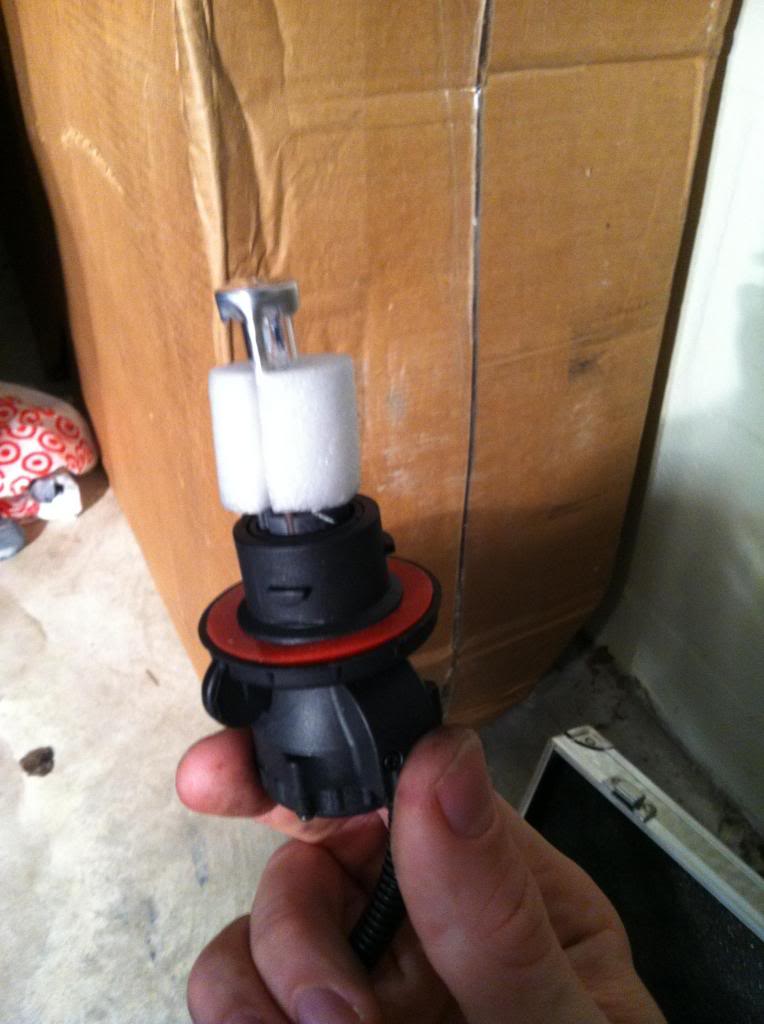
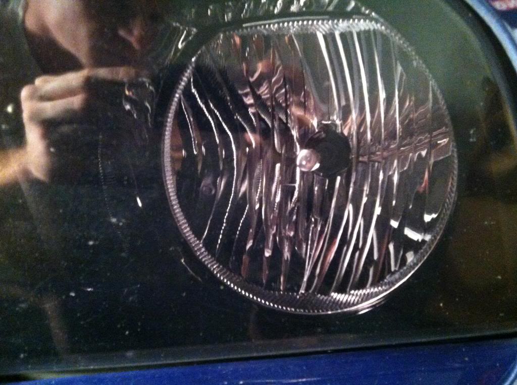
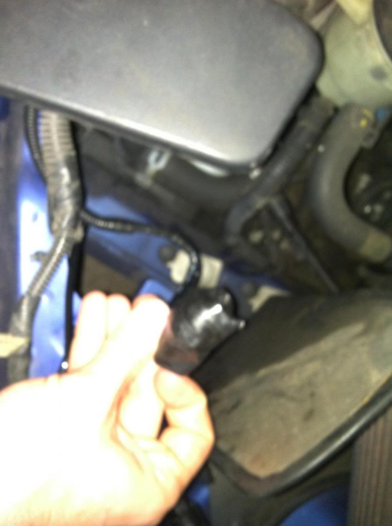
4) Remove light covering and install HID bulbs. The process is the same as installing regular lights (counter clockwise turn to remove, clockwise to install). Don't touch the bulb with your fingers! Install both driver and passenger side bulbs
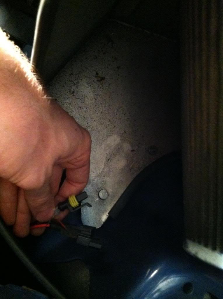
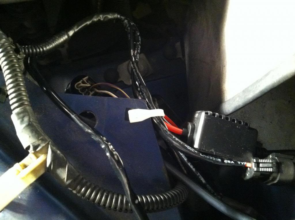
5) Here are the two connectors that will be attached to the ballast. Not pictured here is one other connection that will attach to the last available connection on the driver's side.
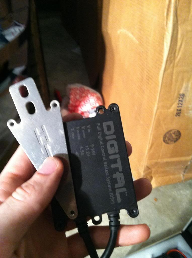
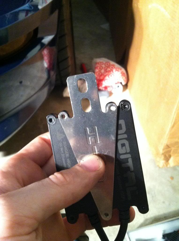
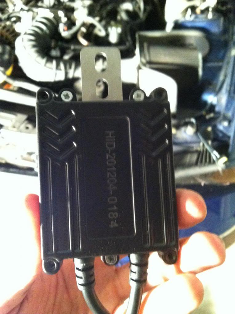
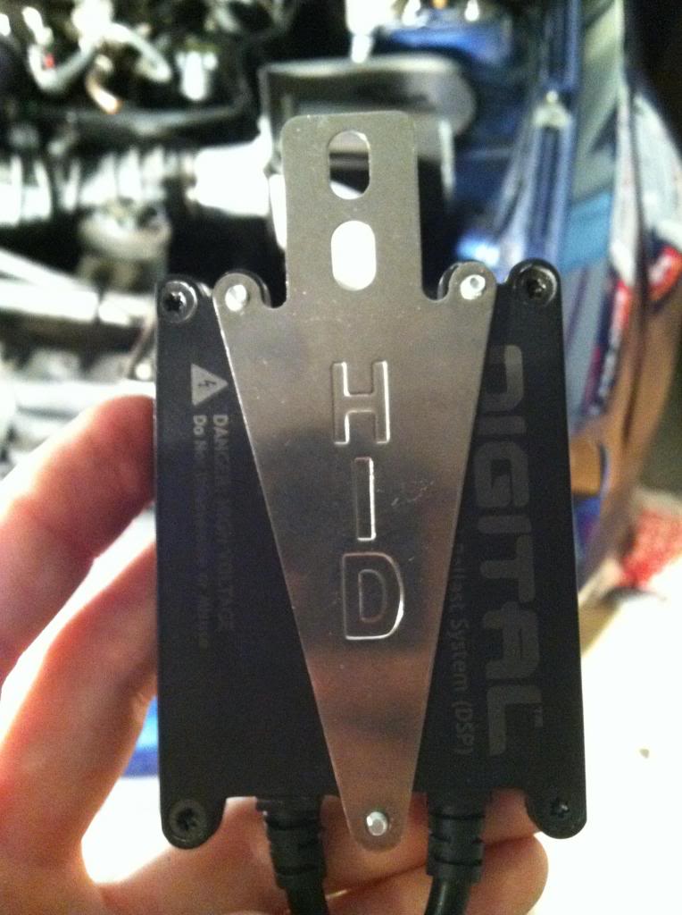
6) Plate and ballast pictured. Install plate to back of ballast as shown using the 3 tiny provided phillips head screws. Do this for both ballasts.
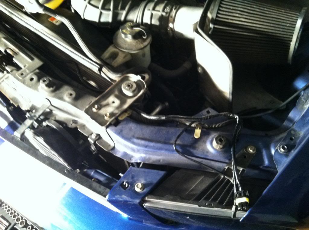
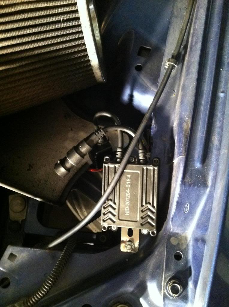
7) Mount ballasts to car. I used the provided nut and bolt for the driver side and a zip tie for the passenger side. Depending on what trim you have and what available holes you have, it may be hard to find a suitable location. My cold air intake did not have a standard nut and bolt connection so I couldn't use this location. I could have dug around for a bolt with a bigger head, but didn't want to spend that time searching around the garage/house for one.
8) Connect both ballasts to the bulbs. Each side will have two connections. DO NOT USE THE DIELECTRIC GREASE! It's literally impossible to connect these wrong. Refer to step 5) for picture.
9) Using the dielectric grease, connect the bulb to the smallest male ends coming from the main harness. When applying the dielectric grease, apply a moderate amount to the pin tips (male end).
10) Again, using the dielectric grease, connect the only other connector from each ballast (male end) to the connector coming from the wiring harness (biggest female connections).
11) Connect the last connector from the relay harness to the stock gray headlight connector on the passenger side.
12) Using electrical tape, seal the end of the driver side stock gray headlight connector. This connector will not be used.
13) Zip tie wires (clean up the look of all those wires).
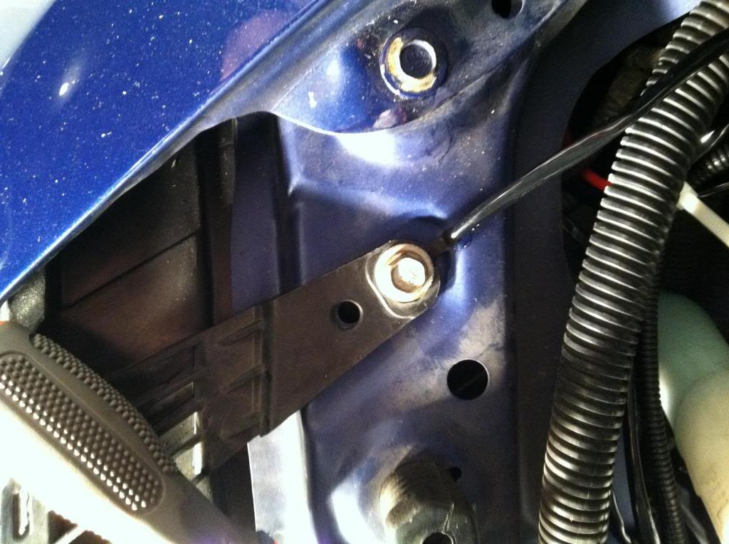
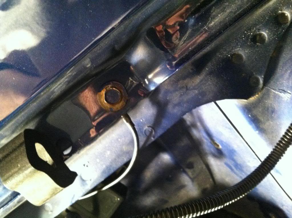
14) Mount grounding wires (3). One on the driver side and two are located on the passenger side. This is where I went wrong the first time. Be sure you have adequate connections! In order to do this, I had to sand the metal contact on the body, dust it clean, apply the dielectric grease and then slip the connectors in and reinsert the bolt. I used the headlight connections (under the plastic) and the last grounding wire for the passenger side utilized a screw on the body holding the fender to the engine bay.
driver side
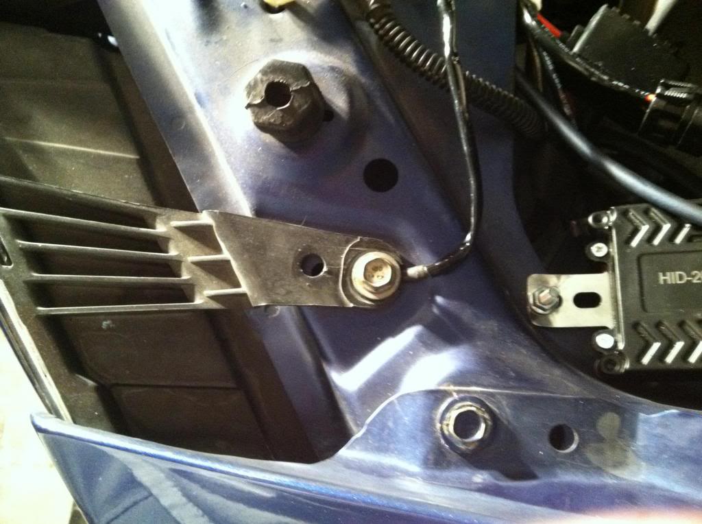
passenger side
passenger side bolt- right next to the passenger strut tower
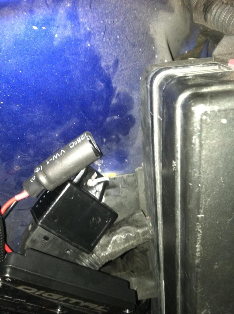
15) Not pictured here because I have not done it yet. It is suggested by Retro Solutions that you heat shrink the capacitor that is connected to the relay harness in order to limit moisture exposure. Why they didn't include the heat shrink material is beyond me. I'll be doing this tomorrow.
16) remove fuse from power line and apply dielectric grease and reinstall. Don't be afraid to use a little muscle, that fuse is in there tight. Connect power line to positive terminal on the battery. In order to do this, I had to cut the circular connection to model the accessory power cord that was already originally connected to the positive terminal because I didn't want to remove the nut on top.
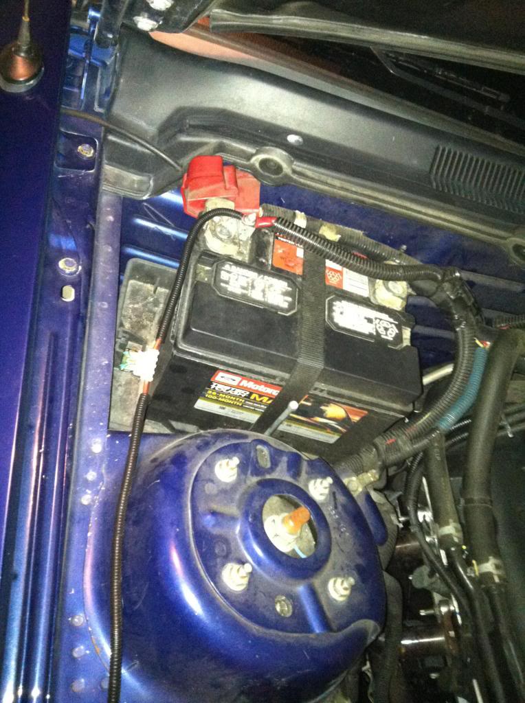
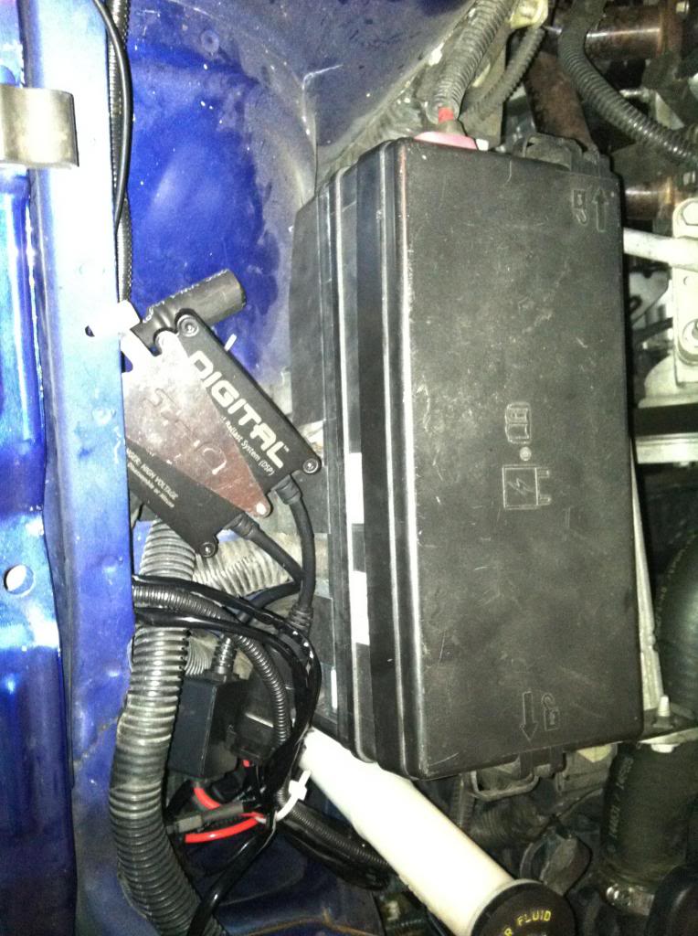
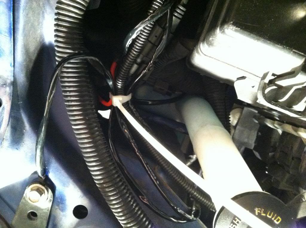
17) Connect your wiring harness to the body. I had almost no connections unless I wanted to drill into the body again like I did for the passenger ballast and I didn't want to hang the wiring harness. So I loosened up a bolt that secured the fuse box and secured it via zip tie
wiring harness end and cylindrical capacitor
18) Ensure all wires and wire looms (especially the one running along the width of the car) is not touching anything that will get hot. I tucked the wire loom underneath the existing wiring loom that runs the length of the radiator.
19) Enjoy your new HIDs
Stock
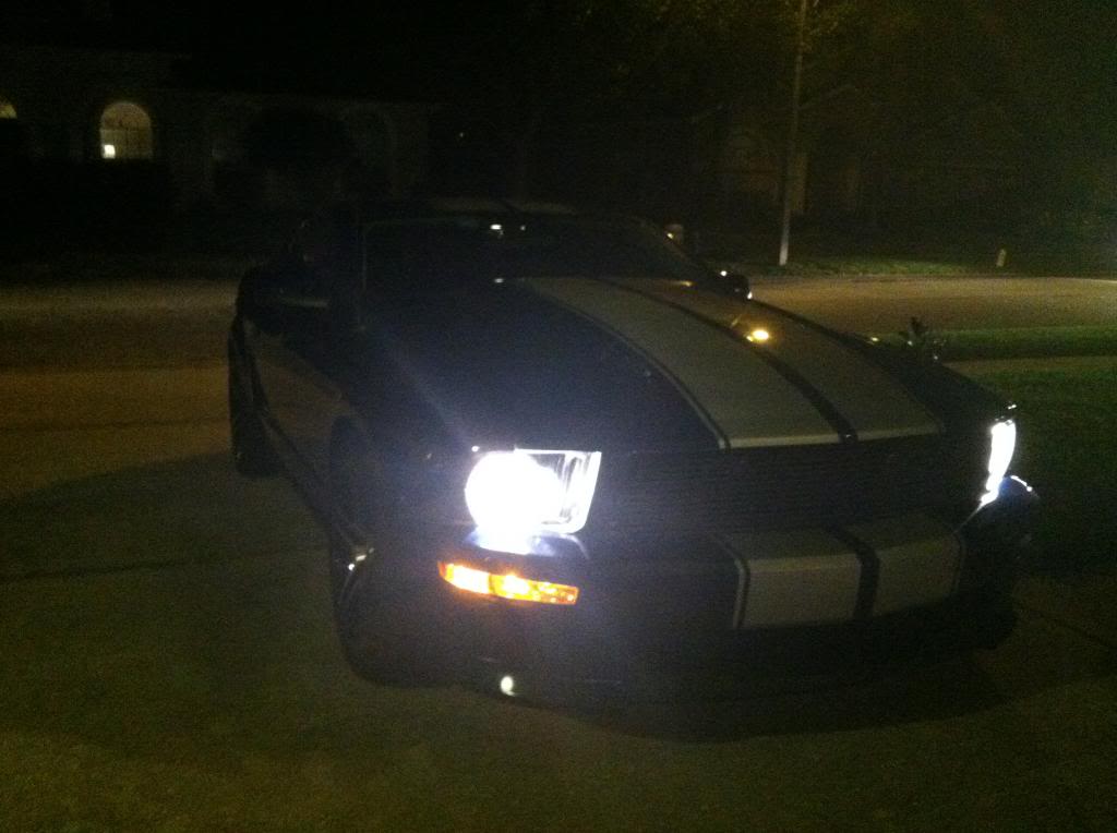
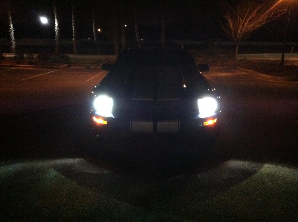
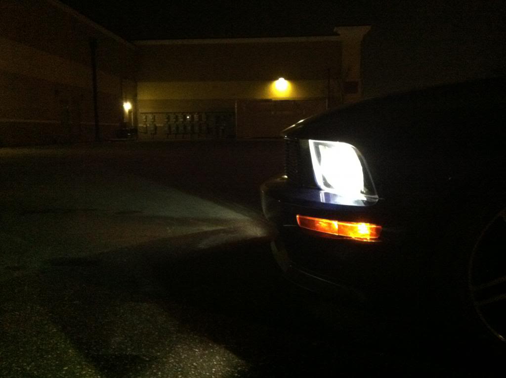
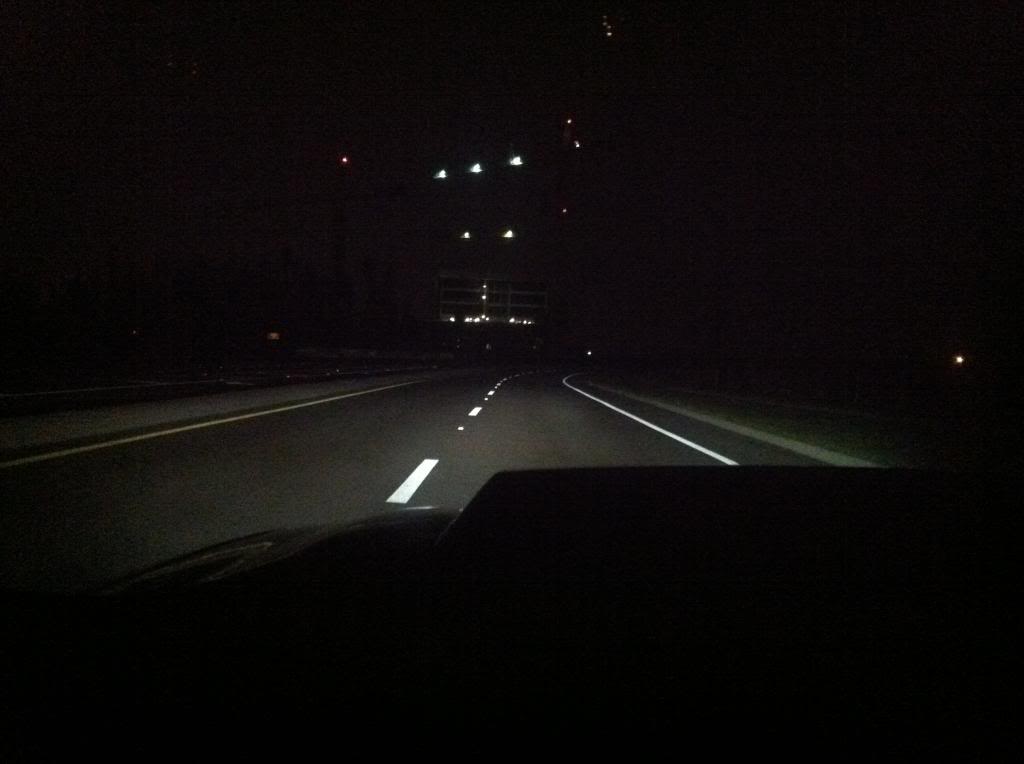
HIDs- Keep in mind these are with tinted headlight housings and taken with an Iphone
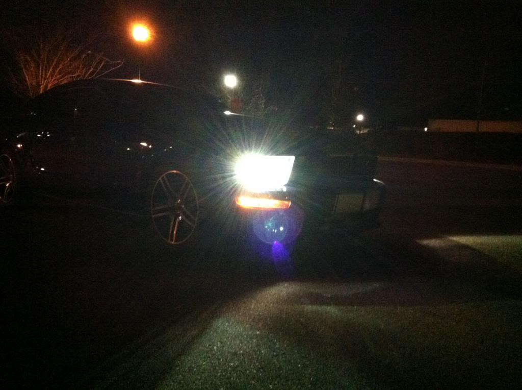
Don't forget to adjust your beams!
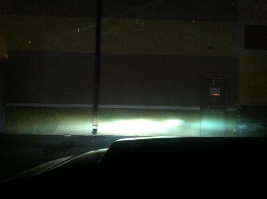
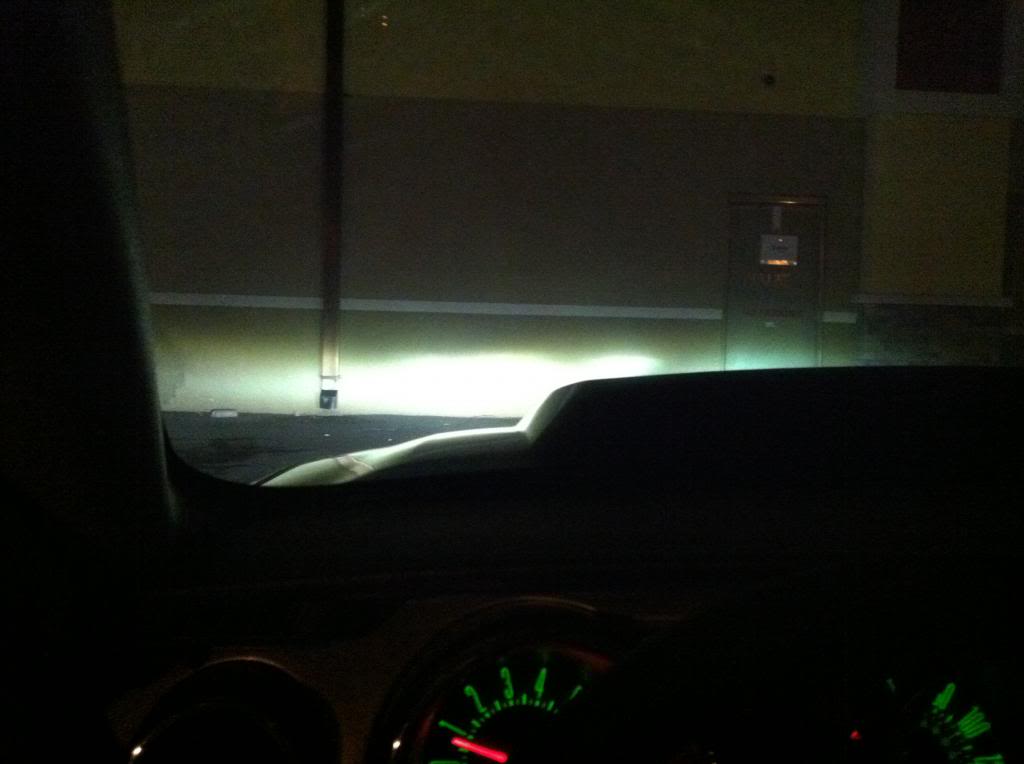
low beams
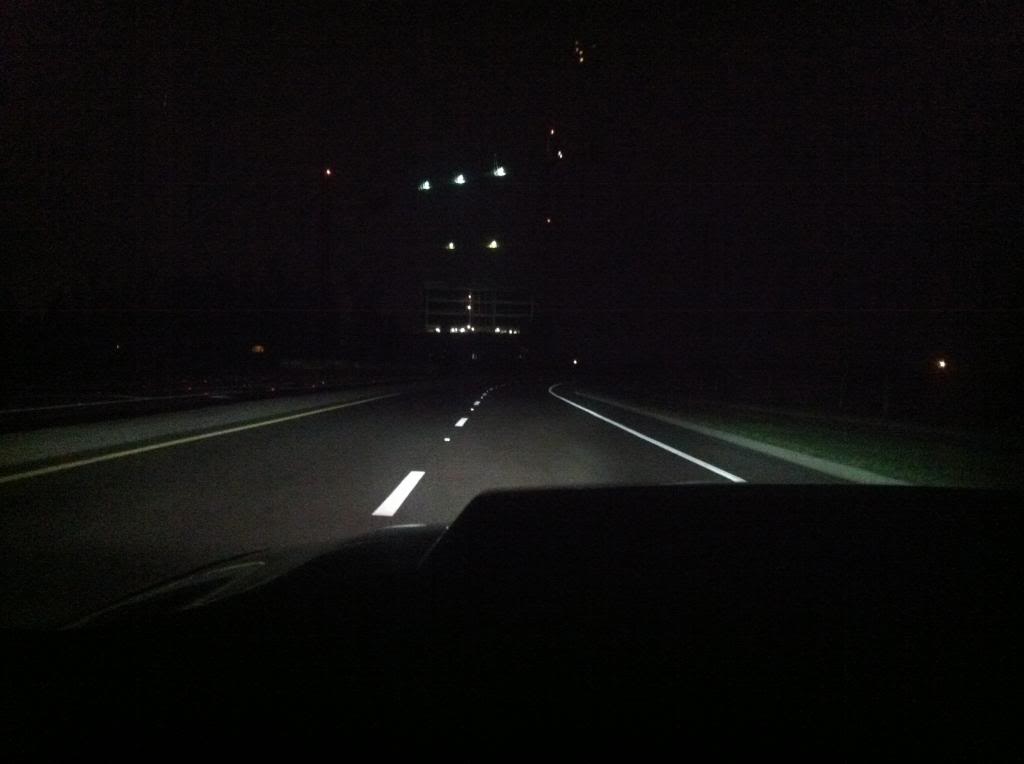
high beams
Begin with reviewing the wiring diagram. Notice how the only connections that DO NOT need the provided dielectric grease to be applied are the connections between each ballast and bulb (4 connectors).
Unboxing: Here is what is provided: 1 relay harness, 2 ballasts and mounting hardware (6 tiny screws to secure plate to balast and 2 bolts/nuts to mount plate to car), 2 bulbs of your chosen intensity, 1 fuse, 1 small bottle of dielectric grease, and 3 small zip ties.
1) Disconnect positive terminal on the battery and ensure proper lighting.
2) Remove radiator cover
3) Thread the long wire loom along the length of the radiator following the existing electrical wire loom.
4) Remove light covering and install HID bulbs. The process is the same as installing regular lights (counter clockwise turn to remove, clockwise to install). Don't touch the bulb with your fingers! Install both driver and passenger side bulbs
5) Here are the two connectors that will be attached to the ballast. Not pictured here is one other connection that will attach to the last available connection on the driver's side.
6) Plate and ballast pictured. Install plate to back of ballast as shown using the 3 tiny provided phillips head screws. Do this for both ballasts.
7) Mount ballasts to car. I used the provided nut and bolt for the driver side and a zip tie for the passenger side. Depending on what trim you have and what available holes you have, it may be hard to find a suitable location. My cold air intake did not have a standard nut and bolt connection so I couldn't use this location. I could have dug around for a bolt with a bigger head, but didn't want to spend that time searching around the garage/house for one.
8) Connect both ballasts to the bulbs. Each side will have two connections. DO NOT USE THE DIELECTRIC GREASE! It's literally impossible to connect these wrong. Refer to step 5) for picture.
9) Using the dielectric grease, connect the bulb to the smallest male ends coming from the main harness. When applying the dielectric grease, apply a moderate amount to the pin tips (male end).
10) Again, using the dielectric grease, connect the only other connector from each ballast (male end) to the connector coming from the wiring harness (biggest female connections).
11) Connect the last connector from the relay harness to the stock gray headlight connector on the passenger side.
12) Using electrical tape, seal the end of the driver side stock gray headlight connector. This connector will not be used.
13) Zip tie wires (clean up the look of all those wires).
14) Mount grounding wires (3). One on the driver side and two are located on the passenger side. This is where I went wrong the first time. Be sure you have adequate connections! In order to do this, I had to sand the metal contact on the body, dust it clean, apply the dielectric grease and then slip the connectors in and reinsert the bolt. I used the headlight connections (under the plastic) and the last grounding wire for the passenger side utilized a screw on the body holding the fender to the engine bay.
driver side
passenger side
passenger side bolt- right next to the passenger strut tower
15) Not pictured here because I have not done it yet. It is suggested by Retro Solutions that you heat shrink the capacitor that is connected to the relay harness in order to limit moisture exposure. Why they didn't include the heat shrink material is beyond me. I'll be doing this tomorrow.
16) remove fuse from power line and apply dielectric grease and reinstall. Don't be afraid to use a little muscle, that fuse is in there tight. Connect power line to positive terminal on the battery. In order to do this, I had to cut the circular connection to model the accessory power cord that was already originally connected to the positive terminal because I didn't want to remove the nut on top.
17) Connect your wiring harness to the body. I had almost no connections unless I wanted to drill into the body again like I did for the passenger ballast and I didn't want to hang the wiring harness. So I loosened up a bolt that secured the fuse box and secured it via zip tie
wiring harness end and cylindrical capacitor
18) Ensure all wires and wire looms (especially the one running along the width of the car) is not touching anything that will get hot. I tucked the wire loom underneath the existing wiring loom that runs the length of the radiator.
19) Enjoy your new HIDs
Stock
HIDs- Keep in mind these are with tinted headlight housings and taken with an Iphone
Don't forget to adjust your beams!
low beams
high beams
Last edited by MadStang40; 01-20-2013 at 11:01 PM.
 01-20-2013, 11:11 PM
#3
No problem Brandon. If you have any questions send me a PM. I know this probably wasn't the best write up as I started to forget to take pictures when making the connections!
01-21-2013, 09:45 AM
#4
5th Gear Member
Join Date: Jun 2008
Location: Brandon, Florida
Posts: 2,616
Would like to add something to the install to cut down on your install time and make it a tad bit easy too. Instead of using the mounting plates for the ballasts just use 3M tape. This will allow you to basically put them where ever you want with out having to drill. I did this with mine works great. Just apply the 3M tape to the bottom of the ballast and press it into place. 
01-21-2013, 04:14 PM
#6
Good call Cutter. I was nervous about mounting with 3M because of temperature but now that I think about it, if it can keep my louvers on, there should t be a problem with mounting two small ballasts.
Thank you Matt. Was hoping the write up would've come out better but forgot to take pictures of the connections before I zip tied them all together but I'm hoping this could serve as a general guide for those interested in the upgrade. I've got a pretty good memory so if anyone has any questions, I'd be happy to answer them via PM
Thank you Matt. Was hoping the write up would've come out better but forgot to take pictures of the connections before I zip tied them all together but I'm hoping this could serve as a general guide for those interested in the upgrade. I've got a pretty good memory so if anyone has any questions, I'd be happy to answer them via PM
01-21-2013, 04:17 PM
#7
5th Gear Member
Join Date: Jun 2008
Location: Brandon, Florida
Posts: 2,616
Good call Cutter. I was nervous about mounting with 3M because of temperature but now that I think about it, if it can keep my louvers on, there should t be a problem with mounting two small ballasts.
Thank you Matt. Was hoping the write up would've come out better but forgot to take pictures of the connections before I zip tied them all together but I'm hoping this could serve as a general guide for those interested in the upgrade. I've got a pretty good memory so if anyone has any questions, I'd be happy to answer them via PM
Thank you Matt. Was hoping the write up would've come out better but forgot to take pictures of the connections before I zip tied them all together but I'm hoping this could serve as a general guide for those interested in the upgrade. I've got a pretty good memory so if anyone has any questions, I'd be happy to answer them via PM
01-22-2013, 03:55 AM
#9

Thread
Thread Starter
Forum
Replies
Last Post
jwog666
Pipes, Boost & Juice
11
12-27-2021 08:09 PM