When you click on links to various merchants on this site and make a purchase, this can result in this site earning a commission. Affiliate programs and affiliations include, but are not limited to, the eBay Partner Network.
Yeah that led connector can go straight onto the clock spring. Best way for is to find the signal wire from the switches on the outside part of the clock spring. That wire will then connect to the metro adapter then just get power to the adapter and you should be good. The adapter is self programming. I can't be too sure if this will work since the cruise buttons are a bit different than radio buttons. Check for the thread on here on how to install a boss Steering wheel. That's the guide I used.
You may have to remove the lower half of the steering column cover or the dash panel in the knee bolster area to see the wires coming off the closkspring.
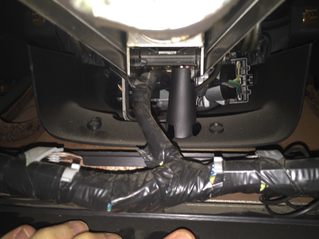
Ok here is what I see under the steering column, picture below. There is a bundle of wires completely wrapped in black tape. It comes to a "T", and one direction heads towards the center console.
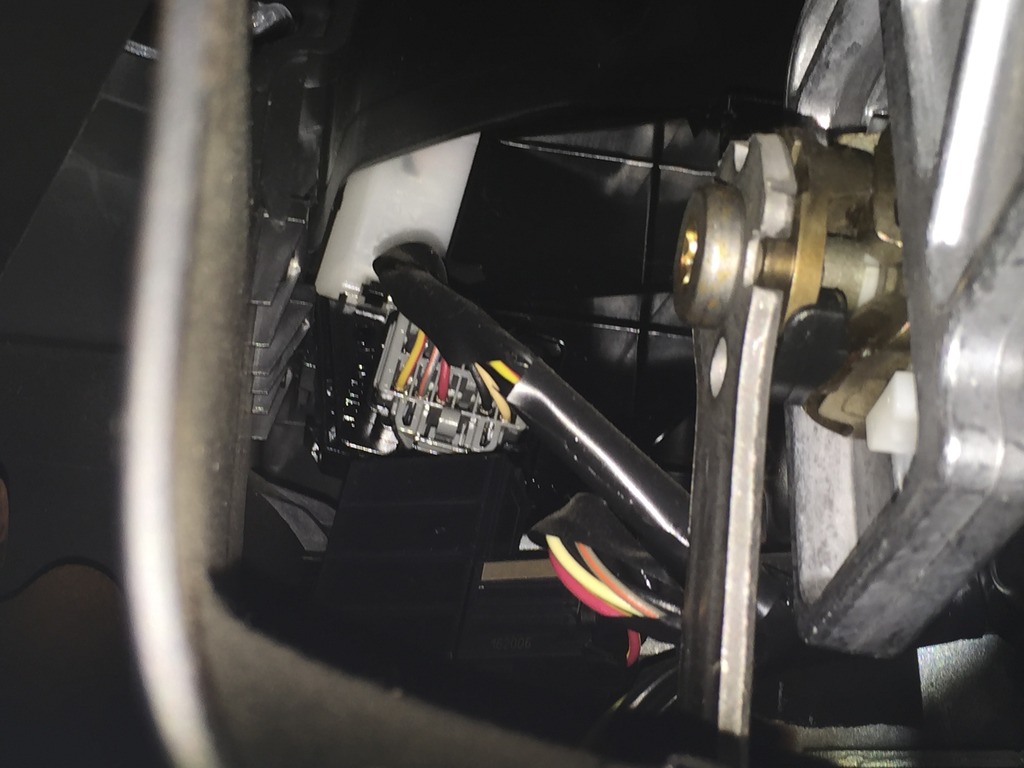
At the steering wheel end, there is a connector on both sides. The one pictured here is on the side towards the center console, and it appears to have a black wire and a tan w/ orange wire. Those colors were for wires coming from the clock spring according to your wiring diagram. But there are a few other wires here too. Is that the connector to the "clock spring"?
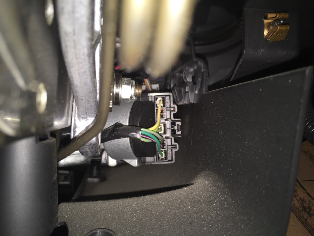
Here is a picture of the connector on the other side of the steering wheel, towards the door.
And here is the wrapped harness bundle as it goes towards the center console.
Yeah that led connector can go straight onto the clock spring. Best way for is to find the signal wire from the switches on the outside part of the clock spring. That wire will then connect to the metro adapter then just get power to the adapter and you should be good. The adapter is self programming. I can't be too sure if this will work since the cruise buttons are a bit different than radio buttons. Check for the thread on here on how to install a boss Steering wheel. That's the guide I used.
Did I identify the "clock spring" correctly above as that grey connector?
This is what the clock spring looks like. the 2 red circles are where the harness from switches would connect to. So the idea would be find out which wire from the switches is putting out the resistance(it will be a different resistance based on what button is pushed) then that wire needs to be traced out to the connector at the bottom of the steering wheel. Splice into that and run it to the steering wheel control adapter. If I get some time I'll see if I can test this out on my own car.
You can touch the multimeter leads to the metal tabs at the back of the plastic connector.
Ok, I'll have to take the bottom cover off the steering wheel but I can try that. I don't really see metal tabs in the picture. Do you just mean insert the probe where the wire enters into the connector?
This is what the clock spring looks like. the 2 red circles are where the harness from switches would connect to. So the idea would be find out which wire from the switches is putting out the resistance(it will be a different resistance based on what button is pushed) then that wire needs to be traced out to the connector at the bottom of the steering wheel. Splice into that and run it to the steering wheel control adapter. If I get some time I'll see if I can test this out on my own car.
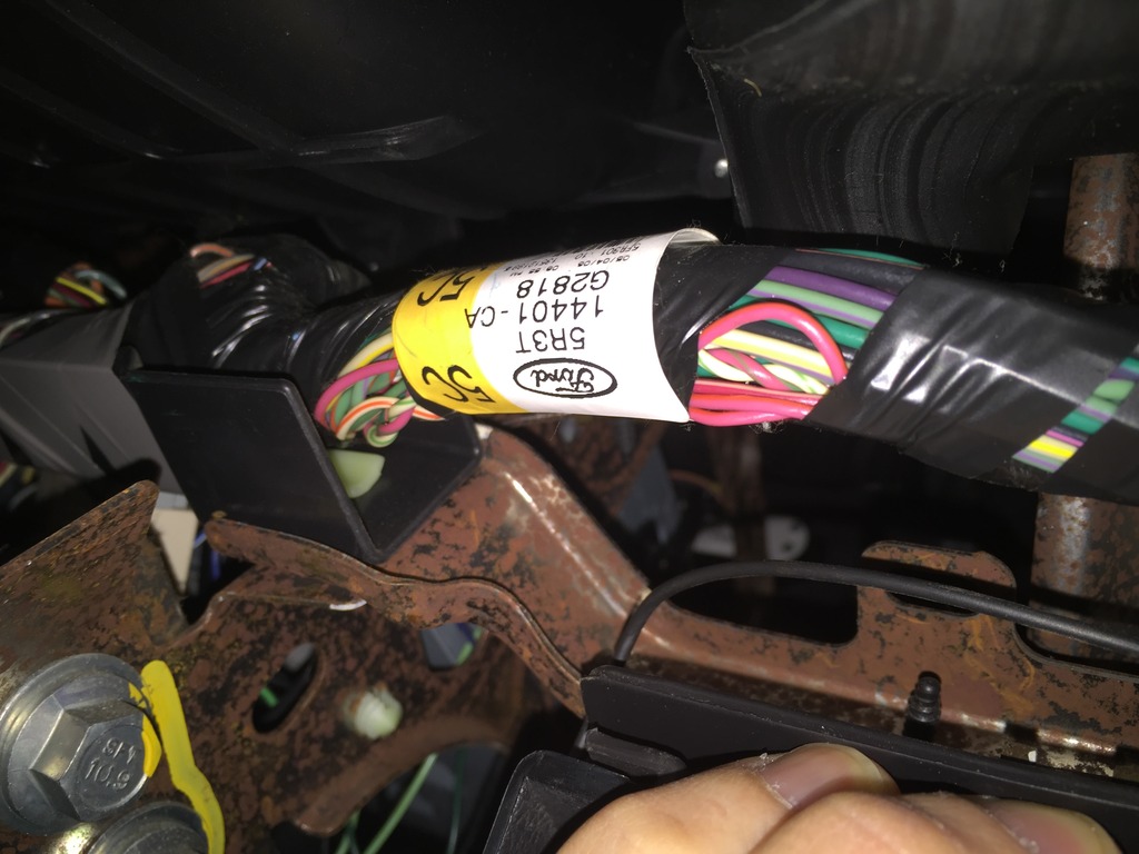
Is this the "connector at the bottom of the steering wheel" that you mean? And once I identify and verify the 2 wires, I'll want to pluck out those 2 wires out from the connector and replace them with the wire for ground and wire to the head unit?
After looking at a few other threads regarding steering wheels, I think what you are trying to do might not be possible. The pac adapter reads resistance of each button press and if that matches the value of what it's looking for then it will send the command to the radio. ex. 200 ohms for volume up, 150 ohms for volume down. I don't know if the buttons for cruise control will show the same resistance as it does for radio controls. (ex + on the cruise control might read 200 ohms but the vol up might read 150 ohms. I don't know the exact values of each so I'm not sure if this will work the way you want it to. As for your 2 previous questions, yes just stick the probe so it touches the metal connector of the wire and yes the is the connector at the bottom of the steering wheel.

 01-28-2016, 10:39 PM