School Boy's research thread
 01-21-2016, 02:37 PM
#11
5th Gear Member
Thread Starter
Join Date: May 2009
Location: kentucky
Posts: 2,241
A couple of links with info on building a irs diff cooler.
http://forums.corral.net/forums/road...hts-input.html
http://www.svtperformance.com/forums...rential-Cooler
http://www.svtperformance.com/forums...OLER-QUESTIONS
IRS Differential Cooler Tech
The Back Story
When we swapped a 1999 Cobra IRS unit into our 1992 Mustang road race car we installed a temperature sending unit in the bottom of the differential case. The gear oil temperatures we experienced far exceeded Ford's maximum permissible temperature of 230� F. It was obvious that a differential cooler would be required to ensure the longevity of the limited-slip differential.
Before we could begin to design our IRS Differential Oil Cooler, we had yet another test to perform. We wanted to see inside the differential case while the car was at speed, so we would know exactly how the gear oil behaved. This knowledge would ensure that we placed the fittings in the differential case in the best locations. Because the IRS differential cover includes the rear mount, we had to do our testing on a solid axle equipped car. We installed a clear plastic differential cover on the solid axle of a 1990 Mustang. We then lifted that car up and ran it in fourth gear at over 100 mph. The clear differential cover allowed us to see inside the differential case and observe the gear oil while the car was in operation. We saw how the ring gear moved the gear oil around, where the oil ended up, and where the oil was completely absent. Based upon our observations, we placed the pump's suction line in the optimum location to pick up gear oil, and to avoid pulling in air. If the pump sucks in air, the gear oil will become aerated, which will reduce its lubricating ability and the effectiveness of the oil cooling system. At MM we know that proper testing is essential to good design, and our IRS Differential Cooler is a prime example of how invaluable testing is.
Our prototype installation had the oil cooler mounted inside the car, in the spare tire well. For our initial tests we did not duct any air to, or away from, the oil cooler. While on track, the gear oil leaving the oil cooler was over 20� F lower than the temperature of the gear oil in the differential case--even without the cooler-mounted fan switched on. Using the supplied fan, and ducting outside air directly to the cooler, will reduce the gear oil temperature even further. The MM IRS Differential Cooler will extend the life of the limited-slip unit, and keep the gear oil below Ford's maximum permissible temperature of 230� F.
 01-21-2016, 02:44 PM
#12
5th Gear Member
Thread Starter
Join Date: May 2009
Location: kentucky
Posts: 2,241
Great discussion about 235/45/17 vs 255/40/17 on 17x8's
http://forums.corral.net/forums/road...-17-17x8s.html
http://forums.corral.net/forums/road...-17-17x8s.html
01-25-2016, 09:45 AM
#13
5th Gear Member
Thread Starter
Join Date: May 2009
Location: kentucky
Posts: 2,241
Originally Posted by MFE
I updated the tech article but here it is
Thanks to qwkcpe for the pics involving the red car.
If you need a refresher on what caster, camber, and toe are, see here: http://www.ozebiz.com.au/racetech/theory/align.html
On to the measurement. First, the caster. In my opinion, this setting is less critical than the rest, and since it's also considerably harder to measure, and often unadjustable, I usually recommend setting it as far positive (strut tops to the rear) as possible, within reason. If the car drifts to one side after all is said and done, remove caster from the side it�s pulling toward. Norm Petersen says "You can make a simple jig from strips of wood or metal to make steering to a specific angle easier and more accurate. I made one for 14.5 degrees (left and right) when I upgraded the homemade camber measurement apparatus to one with a pivot, two magnetic levels, and a dial indicator for easier reading and less math. For 14.5 degrees, caster = 2.0 x (camber difference)." In other words measure the camber with the wheels turned 14.5 degrees left, then 14.5 degrees right, and multiply the difference in measurements by 2 and that's your caster. I drive a fox body and I just set it all the way back. One of these days I'll measure it.
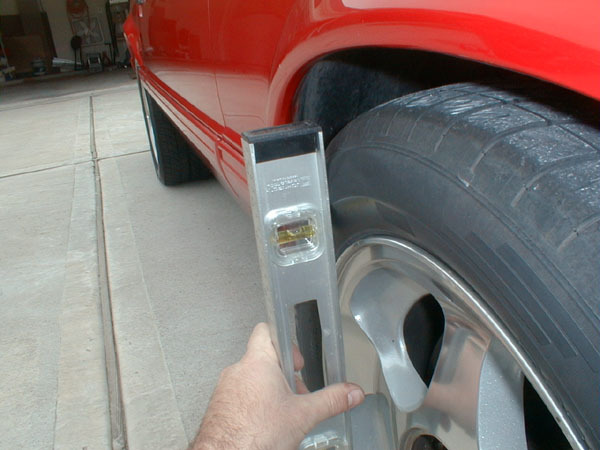
Next, the camber. Easy. You just want to measure how far out of vertical the wheels are. With the car parked on a level floor and with the wheels pointed so they�re straight ahead (regardless of steering wheel position, you can fix that later, just go where you know the car tracks straight ahead), place a construction level against the bottom lip of one front wheel. Hold it so the level indicates perfect vertical, then using a ruler or tape measure, measure the distance from the edge of the level to the top edge of the wheel. See the end for how to convert this measurement into camber degrees.
Note: If you can't get a level solidly against the wheel, here are two options:
1) Cut a length of straight 1x4 or 2x4 wood exactly the diameter of the lip of your wheel to use as a standoff for your level
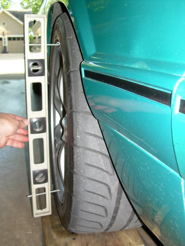
2) as seen in the camber pic on the green car, get some 3/16-inch diameter �all-thread� at the hardware store (rod that's completely threaded, end to end) and cut a couple of 4-inch lengths of it. Drill holes in the frame of your level or in your standoff so that they match up with the diameter of the lip of your wheels, and tap them for the all-thread. Insert the all-thread in the holes to make leveling screws, and holding the level up to your wheel, adjust the screws so the level is perfectly perpendicular. Using a ruler or calipers, measuere the length of each screw. Subtract the shorter one from the longer one, and the result is your distance out-of-vertical. Use the chart at the end to convert to camber degrees.
Using leveling screws:
Now, onto the Toe setting, always done last because camber can have such a dramatic effect on it: You're measuring how far the wheels are toe-'d out or toe'd in, which means you want to compare the distance between the fronts of the wheels and the distance between the rears of the same wheels. Specifically between reference points halfway up the front of the wheels and halfway up the backs of the wheels. You usually can�t just measure across between these points because the car gets in the way, so you need a �caliper� of some sort to transfer these points down to the ground level for measurement. This is easy to make out of a nice straight 8-foot length of 1x2 lumber and a couple of shelf brackets. Or, a shelf bracket and a square.
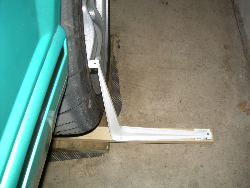
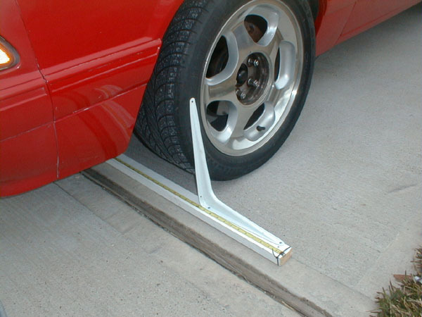
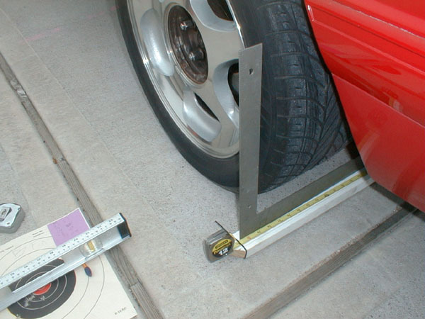
I set the rail under the car so it runs side to side, align the locked bracket with a specific portion of the wheel (or, alternatively, the tire tread) halfway up the back of the tire, then position the other end of the rail to take a measurement. Before I measure, I go back and make sure the fixed end of the rail is still in position because it�s easy to move as you position the other end.
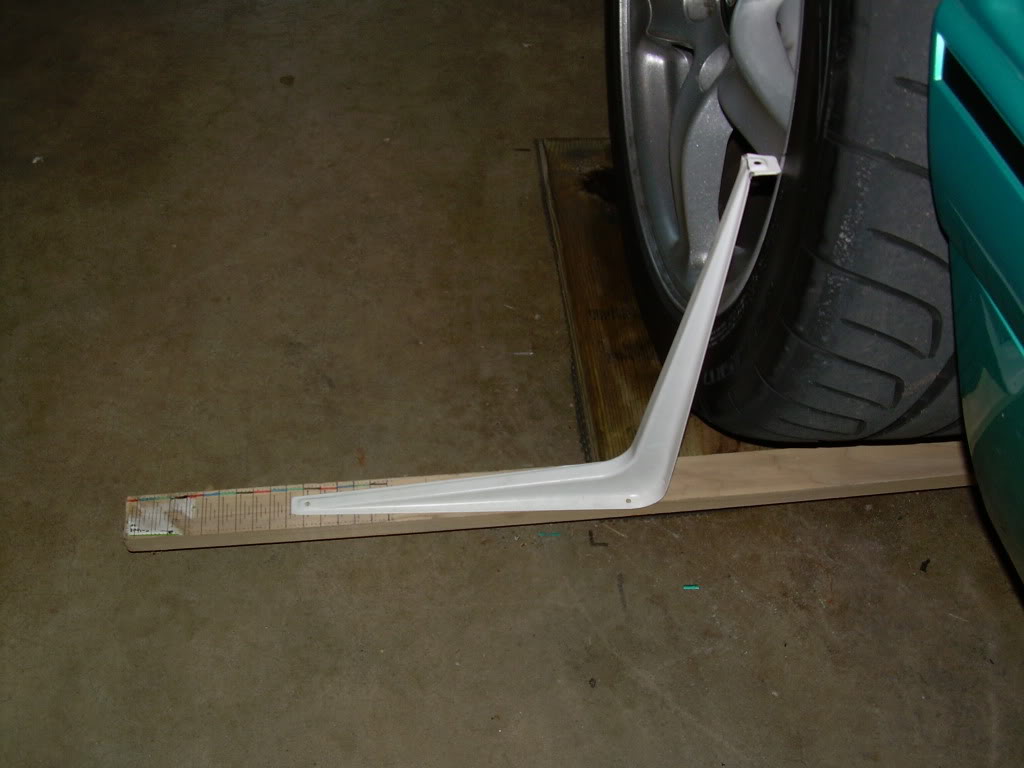
Then I place the slider bracket on the other end and match it up against the same part of the wheel or tire as the bracket on the other side of the car. Make note of the measurement.
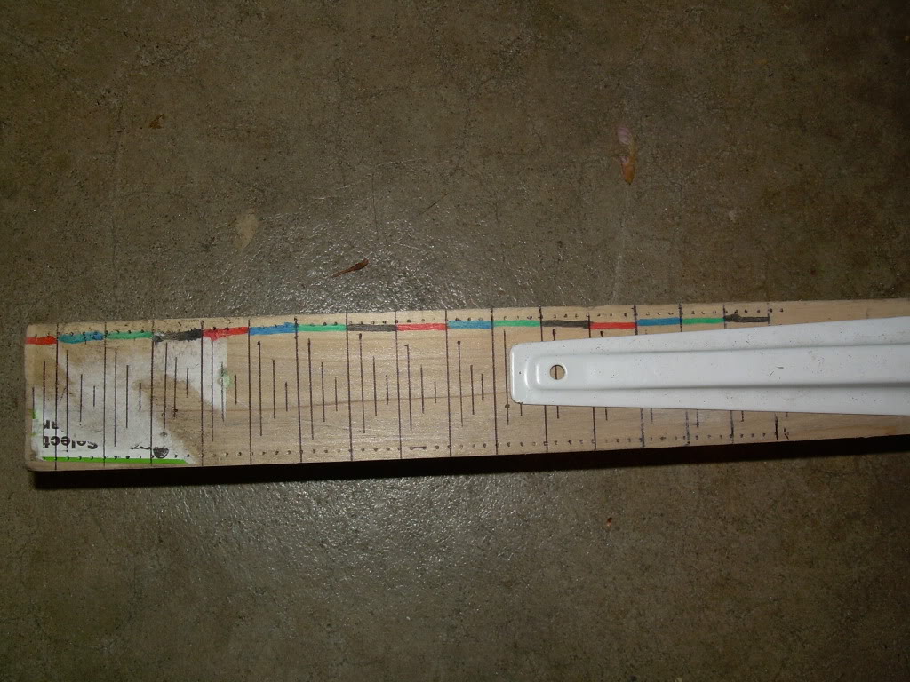
Now bring the rail to the front of the tires and make another measurement the same way. The difference between the two distances, front and rear, is toe. I pre-marked the rail in 1/16th increments where the slider would go but in any case that�s how you do it. If you use this bracket device you�ll have to be precise about how the �slider� bracket sits on the rail to maintain accuracy.
Adjusting the toe is easy, at least on a Mustang. You probably don�t even need to raise the car. By holding the outer tie rod end with some vice grips or channel-locks, take a 7/8 wrench and loosen the jamnut. Then use pliers or a 14mm wrench on the tie rod itself to turn it inward or outward, then hold the assembly still while you tighten the jamnut. A little goes a long way, and if the wheel was crooked now�s your chance to fix it. One full turn of a tie rod should be 1/16th inch of toe change. If you need to toe the wheels in from where they are, start with the wheel opposite where the steering wheel is pointing. In other words if the wheel points to the left, take toe out of the right wheel. If you don�t need to make a toe adjustment but you do need to straighten the wheel, add a little toe to the wheel on the side it points to and take the exact same amount out of the other side until the steering wheel runs straight.
Here's a chart for converting inches of camber into degrees of camber, depending on the size of your wheels.

I updated the tech article but here it is
Thanks to qwkcpe for the pics involving the red car.
If you need a refresher on what caster, camber, and toe are, see here: http://www.ozebiz.com.au/racetech/theory/align.html
On to the measurement. First, the caster. In my opinion, this setting is less critical than the rest, and since it's also considerably harder to measure, and often unadjustable, I usually recommend setting it as far positive (strut tops to the rear) as possible, within reason. If the car drifts to one side after all is said and done, remove caster from the side it�s pulling toward. Norm Petersen says "You can make a simple jig from strips of wood or metal to make steering to a specific angle easier and more accurate. I made one for 14.5 degrees (left and right) when I upgraded the homemade camber measurement apparatus to one with a pivot, two magnetic levels, and a dial indicator for easier reading and less math. For 14.5 degrees, caster = 2.0 x (camber difference)." In other words measure the camber with the wheels turned 14.5 degrees left, then 14.5 degrees right, and multiply the difference in measurements by 2 and that's your caster. I drive a fox body and I just set it all the way back. One of these days I'll measure it.
Next, the camber. Easy. You just want to measure how far out of vertical the wheels are. With the car parked on a level floor and with the wheels pointed so they�re straight ahead (regardless of steering wheel position, you can fix that later, just go where you know the car tracks straight ahead), place a construction level against the bottom lip of one front wheel. Hold it so the level indicates perfect vertical, then using a ruler or tape measure, measure the distance from the edge of the level to the top edge of the wheel. See the end for how to convert this measurement into camber degrees.
Note: If you can't get a level solidly against the wheel, here are two options:
1) Cut a length of straight 1x4 or 2x4 wood exactly the diameter of the lip of your wheel to use as a standoff for your level
2) as seen in the camber pic on the green car, get some 3/16-inch diameter �all-thread� at the hardware store (rod that's completely threaded, end to end) and cut a couple of 4-inch lengths of it. Drill holes in the frame of your level or in your standoff so that they match up with the diameter of the lip of your wheels, and tap them for the all-thread. Insert the all-thread in the holes to make leveling screws, and holding the level up to your wheel, adjust the screws so the level is perfectly perpendicular. Using a ruler or calipers, measuere the length of each screw. Subtract the shorter one from the longer one, and the result is your distance out-of-vertical. Use the chart at the end to convert to camber degrees.

Using leveling screws:

Now, onto the Toe setting, always done last because camber can have such a dramatic effect on it: You're measuring how far the wheels are toe-'d out or toe'd in, which means you want to compare the distance between the fronts of the wheels and the distance between the rears of the same wheels. Specifically between reference points halfway up the front of the wheels and halfway up the backs of the wheels. You usually can�t just measure across between these points because the car gets in the way, so you need a �caliper� of some sort to transfer these points down to the ground level for measurement. This is easy to make out of a nice straight 8-foot length of 1x2 lumber and a couple of shelf brackets. Or, a shelf bracket and a square.


I set the rail under the car so it runs side to side, align the locked bracket with a specific portion of the wheel (or, alternatively, the tire tread) halfway up the back of the tire, then position the other end of the rail to take a measurement. Before I measure, I go back and make sure the fixed end of the rail is still in position because it�s easy to move as you position the other end.
Then I place the slider bracket on the other end and match it up against the same part of the wheel or tire as the bracket on the other side of the car. Make note of the measurement.
Now bring the rail to the front of the tires and make another measurement the same way. The difference between the two distances, front and rear, is toe. I pre-marked the rail in 1/16th increments where the slider would go but in any case that�s how you do it. If you use this bracket device you�ll have to be precise about how the �slider� bracket sits on the rail to maintain accuracy.

Adjusting the toe is easy, at least on a Mustang. You probably don�t even need to raise the car. By holding the outer tie rod end with some vice grips or channel-locks, take a 7/8 wrench and loosen the jamnut. Then use pliers or a 14mm wrench on the tie rod itself to turn it inward or outward, then hold the assembly still while you tighten the jamnut. A little goes a long way, and if the wheel was crooked now�s your chance to fix it. One full turn of a tie rod should be 1/16th inch of toe change. If you need to toe the wheels in from where they are, start with the wheel opposite where the steering wheel is pointing. In other words if the wheel points to the left, take toe out of the right wheel. If you don�t need to make a toe adjustment but you do need to straighten the wheel, add a little toe to the wheel on the side it points to and take the exact same amount out of the other side until the steering wheel runs straight.
Here's a chart for converting inches of camber into degrees of camber, depending on the size of your wheels.
 01-25-2016, 06:10 PM
#14
5th Gear Member
Thread Starter
Join Date: May 2009
Location: kentucky
Posts: 2,241
I put the 10.5" 900# springs with poly isos top and bottom
(from stangsuspension.com) and the ride is even right around 26.5" in the rear ground to fender well. Feels good with the 400# front coil overs. I need to tweak the dampening a little.
If you want a set, send an e-mail to allennaylor@bellsouth.net
He said he's got a few 800, 900, 950s & 1000 in 10.5".
the cobra R's in the rear are only 700 lbs and they are linear
Local autocrosser seems to be doing well with 1000lb conventional springs on all four corners of his 03 Cobra.
01-27-2016, 07:42 PM
#16
5th Gear Member
Thread Starter
Join Date: May 2009
Location: kentucky
Posts: 2,241
03 10th anniv 17x9
03/04 Cobra 17x9
95 Cobra R58 17x9
Ford FR500 17x9
98 SVT cobra wheels 17x8
Steeda Ultralites 17x9
Enkei RPF1 17x9, 17x9.5, 17x10
99/01 Cobra 17x8 (need small spacer to clear spokes)
03/04 Cobra 17x9
95 Cobra R58 17x9
Ford FR500 17x9
98 SVT cobra wheels 17x8
Steeda Ultralites 17x9
Enkei RPF1 17x9, 17x9.5, 17x10
99/01 Cobra 17x8 (need small spacer to clear spokes)
02-05-2016, 08:33 AM
#17
5th Gear Member
Thread Starter
Join Date: May 2009
Location: kentucky
Posts: 2,241
If the car oversteers under part throttle with the IRS, you do not have enough camber in it.
With a solid axle, under cornering, both rear tires are essentially at 0 camber when cornering. When you install the IRS, the inside tire has positive camber due to body roll, the outside tire has negative camber due to body roll. The net result is a loss of rear cornering grip. You will need to run at least -1.25 degrees to get good cornering. -0.8 degrees is stock. I would look at that before yanking the rear swaybar.
Jack Hidley
Maximum Motorsports Tech Support
03-19-2016, 01:35 PM
#18
5th Gear Member
Thread Starter
Join Date: May 2009
Location: kentucky
Posts: 2,241
THE ARGUMENT AGAINST CROSS-DRILLED VENTED ROTORS (by Marcus Blair Fitzhugh, � 2007, reformatted for clarity)
They're for looks. OK, maybe removing material is good for reducing un-sprung weight, but that's about it. It doesn't do anything for heat dissipation.
The front discs on my car are vented. They're vented on every car that I know of. When a vented disc is spinning, it pulls air from the center of the disc, through the channels (which are called vanes), and out the rim of the rotor. The vanes in a Mercedes-Benz rotor are also curved. That's because the engineers who design rotors know that curved vanes move cooling air more efficiently than straight vanes, which are less expensive to manufacture. This cooling air moves in a radial direction. We can view the spinning rotor as an efficiently designed air pump.
The cross drilled holes in the disc must aid in this cooling design, right? Not quite.
Let's think about what happens. Air flow follows the path of least resistance.
Does the air that's flowing from the center of the rotor to the path of least resistance go to the wide open vanes, or make a 90� turn, to holes that are drilled axially in the rotor?
So, since the holes aren't there to pull air in, and they don't aid in pushing the air out, you may be wondering why they were invented.
Cross drilled rotors were originally designed to cure a problem called out-gassing. Outgassing was a problem where pads would overheat, and the binding material (glue) would melt down and vaporize.
This vapor became trapped between the pad and the rotor, making the pad to float on a layer of vapor.
The purpose of cross-drilled rotors was to allow the gas to escape. The key word there is “was”.
Better high performance pad design has eliminated this problem.
If you simply can't bring yourself to believe that cross-drilled rotors are all hype, consider this.
Why aren't cross-drilled rotors used in NASCAR, Formula 1, Automobile Club de l'Ouest (ACO), or ALMS?
If drilling holes in rotors was the hot ticket, at least one team in one of those associations would use them.
Some people will claim, "Motorcycles use them!"
This is true, however, if you look carefully at a motorcycle disc you will notice they aren't vented, motorcycles use solid discs.
They can use solid discs because they carry one eighth the weight of a car.
If you drive a 400 pound car, solid, cross-drilled discs may be an option.
Still have doubts? Here are some quotes from brake engineers, brake manufacturers, and automotive publications in regard to cross-drilled, slotted, and plain rotors.
AP Racing: "Grooves improve 'cleaning' of the pad surfaces and result in a more consistent brake performance.
Grooved discs have a longer life than cross-drilled discs."
Baer: "What are the benefits to Cross-drilling, Slotting, and Zinc-Washing my rotors?
“In years past, cross-drilling and/or Slotting the rotor for racing purposes was beneficial by providing a way to expel the gasses created when the bonding agents employed to manufacture the pads.
However, with today’s race pad technology, out-gassing is no longer much of a concern.
Slotted surfaces are what Baer recommends for track only use.
Slotted only rotors are offered as an option for any of Baer's offerings."
Darrick Dong; Director of Motorsports at Performance Friction: "Anyone that tells you that drilling makes the disc run cooler is smoking crack."
Waren Gilliand: (Mr. Gilliland is a well-known brake engineer in the racing industry and has more than 32 years experience in custom designing brake systems ...he became the main source for improving the brake systems on a variety of different race vehicles from midgets to NASCAR Winston Cup cars.) "If you cross drill one of these vented rotors, you are creating a stress riser that will encourage the rotor to crack right through the hole. Many of the rotors available in the aftermarket are nothing more than inexpensive offshore manufactured stock replacement rotors, cross drilled to appeal to the performance market. They are not performance rotors and will have a corresponding high failure rate"
Grassroots Motorsports: "Cross-drilling your rotors might look neat, but what is it really doing for you?
Well, unless your car is using brake pads from the '40s and 50s, not a whole lot.
Rotors were first drilled because early brake pad materials gave off gasses when heated to racing temperatures, a process known as gassing out.
It was an effective solution, but today's friction materials do not exhibit the some gassing out phenomenon as the early pads.
“Contrary to popular belief, they don't lower temperatures, (in fact, by removing weight from the rotor, they can actually cause temperatures to increase a little.)
“These holes create stress risers that allow the rotor to crack sooner, and make a mess of brake pads--sort of like a cheese grater rubbing against them at every stop.
Want more evidence? Look at NASCAR or F1.
You would think that if drilling holes in the rotor was the hot ticket, these teams would be doing it. “
“Slotting rotors, on the other hand, might be a consideration if your sanctioning body allows for it.
Cutting thin slots across the face of the rotor can actually help to clean the face of the brake pads over time, helping to reduce the glazing often found during high-speed use which can lower the coefficient of friction.
“While there may still be a small concern over creating stress risers in the face of the rotor, if the slots are shallow and cut properly, the trade-off appears to be worth the risk, (have you looked at a NASCAR rotor lately?)”
Power Slot: "At one time the conventional wisdom in racing circles was to cross-drill brake rotors to aid cooling and eliminate the gas emitted by brake pads. However, today's elite teams in open wheel, Indy and Trans Am racing are moving away from crack prone, cross-drilled brake rotors in favor of rotors modified with a fatigue resistant slotting process."
Stop Tech: "StopTech provides rotors slotted, drilled or plain. For most performance applications slotted is the preferred choice. Slotting helps wipe away debris from between the pad and rotor as well as increasing the "bite" characteristics of the pad. “A drilled rotor provides the same type of benefit, but is more susceptible to cracking under severe usage. Many customers prefer the look of a drilled rotor and for street and occasional light duty track use they will work fine. “For more severe applications, we recommend slotted rotors." (Note that even though Stop Tech sells both drilled and slotted rotors they do not recommend drilled rotors for severe applications.) Wilwood: Q: “Why are some rotors drilled or slotted?” A: “Rotors are drilled to reduce rotating weight, an issue near and dear to racers searching for ways to minimize un-sprung weight. Drilling diminishes a rotor's durability and cooling capacity"
Last edited by school boy; 03-19-2016 at 01:41 PM.
07-10-2016, 07:35 PM
#19
5th Gear Member
Thread Starter
Join Date: May 2009
Location: kentucky
Posts: 2,241
FMS M2300K Brake Install
The brakes on the Mustang as supplied from the factory are not up to snuff. Serious performance enthusiast know this fact and take steps to improve the Mustangs braking system. These improvements can range from something simple, like replacing stock pads and shoes with performance units, to a complete build up. Either way, one unbreakable tenet of a good braking system is: Good Brakes Are Not Cheap --end of story. While many, including myself, try to complete an upgrade on a budget, the reality is that one must be willing to dole out some hard cash if he/she desires the top end stuff. This tech article is a review of the installation of the FMS Cobra brake kit on this 91 SSP Mustang. I found the FMS kit instructions (located at the bottom of the article) to be sparse at best. There are plenty of pictures here and some tips on the installation that I learned along the way or gathered from experienced installers. The technical information presented here is simplified in form. If you feel you cannot follow this article or are in doubt, it may be smart to hire a mechanic to install the brakes.
Plan of Attack
Once you have finally located and received your kit (They are on back order from FRPP nationwide at the time of installation), you need to come up with a plan. I decided to knock out the under-the-hood work which includes installation of the power booster, master cylinder, and proportioning valves. After this, I began to install the rear brake set. Finally, I installed the front brake set. No matter what order, it seems clear that a step by step approach will make the overall installation manageable. Another consideration should be tools and materials. I gathered all the tools and materials that would need before installation. This makes the install go smooth and you will not find yourself making 15 trips to the parts store and/or begging to barrow tools mid project. In any case, it is wise to have some sort of plan in mind when doing a brake job of this size and nature. Without such, frustration will prevail and one's visions of a great install will only manifest as a giant hack job --not what you want to hear after laying out upwards of $2000. for a brake set.
Under-the-Hood
This part of the install includes the new power booster, master cylinder, and proportioning valve. First, remove the stock master cylinder and pig tails, followed by the stock booster. Many have foregone installation of the massive Cobra power booster because of tall tails of needing to acquire a big hammer and going postal on the strut tower to gain the required clearance necessary to install the monster booster. Even the instructions supplied with the kit note that "some relieving of the strut tower may be necessary". Well, I did not find such to be the case on this 91 LX coupe but sometime in 1989, the strut tower was redesigned so your results may vary. While it was tight, I never had to swing the hammer. Instead, I was fortunate to receive a tip and such proved to be the trick. The power booster is mounted with four studs that fit in holes in the firewall. After getting all the wires, lines, etc. out of the way, I discovered that the booster almost fit. The problem was that I could not slide the studs in straight, but rather they had to go in on an angle due to the size of the booster. This angle resulted in the top right stud (passenger's right) getting caught up in the hole and not allowing the booster to slide in. The trick is to enlarge this hole with a drill or small die grinder. This allows the stud to have more play. Do not remove anymore then necessary or booster alignment problems may result. I took my time and worked the hole, test fit the booster, etc. until I was able to slide the booster in. The total time of my work here was an hour. In fact, the most difficult part was getting up under the dash to remove and reinstall the retaining nuts.
The next step is to replace the stock proportioning valve with the one supplied with the kit. You must "gut" the supplied proportioning valve and install the supplied solid end plug to get the modified proportioning valve. The instructions supplied with the kit are pretty clear on this procedure. You will find that in some applications the proportioning valve mounts to the fender well via a stud and one nut. There is also a small metal tang that locates the valve mount. With the new prop. valve, you will find that instead of one, there are two mounting studs. To mount the valve properly, it is necessary to obtain the second nut. The additional stud passes through the fender well where the locating tang once was. This is pretty clear when looked at on the car. It is best to install the modified prop. valve and refit the stock chassis hard lines before installing the new master cylinder as there is little room for the tools required to reflare the brake hard lines. As the kit instructions indicate, the stock left front brake line must be rerouted to the rear port of the new prop. valve. Ok, not big deal, right? Well in my case I found that my tubing cutter would not allow me to cut the line and reflare it leaving enough line to make the connection properly. There was simply not enough space on the line for me to fit my cutter in the best spot. My resolve was to begin with a new section of hard-line bending and flaring as necessary. I used the stock hard-line as a guide and essentially copied the bends making it appear as a factory line with minimal effort. It is also necessary to replace the top rear line fitting on the stock arrangement as it is a different size than required for the new valve. Fortunately, I had the proper fitting handy as one wasn't supplied with the kit. These fittings are easily obtainable at your local auto parts house. I was able to cut this line, slide the required fitting on, and reflare it with no problems. A note of caution here: flaring brake lines is not difficult, but does take a certain amount of practice and finesse. I have had experience flaring brake lines in the past and will readily admit that my firsts attempts looked like crap and leaked. Don't despair if you can't get a good sealing flare the first time. In the past, I practiced on an old piece of hard-line perfecting my ability before applying my work to a car I would be riding in. No joke here folks, get your flaring skills down and use a good flaring tool kit. In addition, save yourself some agony and invest in or borrow a set of flare wrenches. It is difficult at best if not impossible to loosen and tighten brake line fittings without flare wrenches.
Next, I installed the new master cylinder. Before connecting the stock pig tails, I bench bled the new master cylinder. This will get brake fluid in the piston bore and eliminate the chance of air getting trapped resulting in a mushy brake pedal and frustration. After this, install the pig tails and make a final check of all line connections for tightness. Finally, install the supplied adjustable prop. valve at the hard-line junction found near the A/C dryer canister along the passenger side firewall. The kit we received had the required adapter fittings and instructions explaining initial valve adjustment. At this point, all the under-the-hood work is complete.
11.65" Rear Disc
The rear disc installation naturally begins with removal of the stock brakes. Get the car safely up on jack stands allowing yourself plenty of room to work comfortably. After pulling the brake drums (a few taps with a hammer will free them up), you will note that the entire brake assembly can be removed by pulling four bolts. It was time to pull the stock axle shafts first. Begin by loosening the rear end cover bolts. Do not remove them entirely or even break the cover seal until they are all loose. Position a suitable drain pan under the rear end pumpkin. I then loosen the bottom four cover bolts almost completely and then gently pried the cover loose until the old axle lube began to drain. Take a break here while letting it sit to drain out well. After it drains, pop the cover off and pull the lock bolt and c-clips. Carefully pull each axle out on either side. I removed the four bolts without disconnecting the parking brake line. I pulled the brake assembly intact and laid it under the car until disconnecting the ebrake cable at the T found under the parking brake lever in the trans tunnel. Once the cables are freed from the chassis, you can slide the whole set from under the car and say good-bye to the stock rear drum brakes. Next, I removed the stock hard lines, tee and soft line from the axle. The kit comes with all new lines and brackets. Before attempting to install the new lines, I laid everything out as it appeared to best fit on the car. The reason for this is all the lines and other loose hardware are not marked and nothing more than a simple puzzle. I installed the new standoff and tee followed by the lines that run along the axle. The soft lines that bridge between the caliper and axle are supplied with a bracket assembly which requires you to drill two holes in each LCA mount above the shock mounting point. One hole is for the #40 torx chassis mount bolt and the other is for a metal locating tang on the bracket. I found it necessary to remove the shock at the lower mount. I took pressure off the shock by placing a jack under the pumpkin and raising it a little. Then I compressed the shock by hand and zip tied it up out of the way. I could then get my drill in a good position. Next, I merely laid the bracket in the desired location and marked my drill points. I drilled the holes, installed the brackets/lines and tightened everything up. If you take your time in replacing and fitting up these lines, the resulting fit and finish will be well worth the effort in final fit and finish.
At this point, it is time to install the new axles, caliper brackets, rotors and calipers. But before doing so, you may wish to spend an extra $5 and replace the axle shaft seals. I felt that while the existing seals looked fine, now would be a good time to replace them as the originals had 95,000 miles on them. I reasoned that for the time and cost involved, it would be a shame to have to pull everything apart a month or two down the road should one of the old seals go south. Install the new axle shafts and reassemble the rear c-clips and axle cover (torqut to 25-35 lb ft). I have always preferred to use quality RTV instead of a gasket to seal the axle cover. Refill the pumpkin with gear oil and do not forget to add friction modifier.
Now it is time to see the rear brakes come together. I decided to paint the caliper mounting brackets as one was received bare, and the other was painted on one side only. This is not necessary, but makes the difference in the final finish. To mount the brackets, you can use the original hardware. I opted to use the bolts, but replaced the nuts with a set that had nylon inserts. For only a buck and a little lock-tite, I know those brackets are not going to come loose or shift down the road. Be sure to apply the recommended torque to the bracket bolts. This is a good time to loosely fit the anti-moan brackets that are attached at the axle via a U bolt which passes under the quad-shock mount. At the caliper bracket, they share the caliper mounting bolts as an anchor. I only hand tightened these brackets as final torque down should come after the calipers are installed. Next, install the dust shields. We had to buy the correct 6mm fine threaded hex bolts and washers as I found none with the kit (the ones sent were totally different in thread pattern). The shields fit on the outside face of the caliper bracket. (Some kits such as SSB rear set-up have them on the inside face of the bracket). You will not be able to install the shields easily if the rotors are in place (voice of experience speaking). Now carefully install the new rotors paying attention not to get them dirty or covered with greasy finger prints. I sprayed the rotors down with brake cleaner and wiped them off to remove the oily film the factory applies to prevent rust. Install a couple of standard lug nuts finger tight to hold the rotor steady as you mount the calipers. New caliper mounting bolts were supplied with the kit. Applying just a dab of lock-tite, torque the caliper bolts to 70-95 lb ft. With the exception of the ebrake cables, the rear brakes are finished.
Ebrake Handle and Cables
The parking brake handle requires modification to defeat the self adjusting mechanism. First remove the handle from the car by removing the shifter bezel and the armrest if so equipped. You will then be able to see 4 screws (two at the front and two at the rear) that hold the upper console to the lower console. Once the screws are removed, carefully lift up on the upper console so that it's possible to disconnect the wires to the power mirrors and to the cigarette lighter. Once the upper console has been removed, you will see that the parking brake handle is held on by two screws to the floor. You must first disconnect the parking brake cable before removing the handle. Since the spring holds tension on the cable, you will have to overcome this by physically turning the spring. Be Careful!! The spring is tight but not too tight. If the spring pops back, make sure your fingers are no where near it. This along with the power brake booster will probably be one of the toughest tasks in this kit only because you are stuck in a car with very poor seating position. Once the spring is disconnected, remove the screw that holds the parking brake indicator switch and the two bolts holding the parking brake to the floor. You will now have to remove the small section of parking brake cable that holds the equalizer on from the bottom.
The parking brake handle must be modified by (1) cutting the end of the adjusting spring off, (2) welding the adjuster to the handle itself and (3) cutting the end of the adjuster so that the parking brake handle will sit all the way to the normal position once it is back in the vehicle. One can see the 3 modifications necessary as diagrammed in the photo. You will have to weld the pawl to the handle with the second from the last tooth engaged (a simple tack weld will work just fine). The end of the spring will also have to be removed and I recommend doing it with a cutoff wheel or a torch because the metal is tough. In this installation, I went ahead and cut the entire spring off to save me from a forseen rattling of a loose spring, but it is not necessary. If you choose to remove the entire spring via torch, remember that the end of the handle is plastic (or leather if your lucky) and it can melt very easily. The final step that is not mentioned in the instructions is to remove the overlapping metal on the pawl. In it's original form, the handle would lift the pawl when released but since we have now welded the pawl to the handle, the overlapping metal now will not let the handle sit all the way down. Cut it with the torch while you have it out. I had a muffler shop do the work for me and they charged me $5.00 so don't struggle with simple tools if you do not have a torch and/or welding equipment.
Next step is to modify the equalizer where the parking brake cable connects to the rear cables. You need to first remove it from the vehicle from underneath. There is a rubber boot that keeps water out of the interior of the car so care should be taken not to rip the little boot as I did. Once the equalizer and cable are out, you will need to cut the end that hooked into the parking brake handle off so that the cable can be seperated from the equalizer. The old cable can be discarded as it will no longer be used. You will need to enlarge the hole that the cable ran through to 11/32" so that the new threaded adjuster will fit through the hole. The equalizer and the new adjuster should now be finished.
Once the modifications to the parking brake handle have been completed, you can now install the new cable onto the handle. Care must be taken to fit the cable to avoid putting a kink in it, take your time! I highly suggest doing this before installing the parking brake handle since you will have an easier time maneuvering the handle to where you need it to be. Once it has been installed, reinstall the handle, making sure the threaded end of the adjuster goes through the rubber boot and to the outside of the car. Reinstall the parking brake warning light switch and the two screws that hold the handle to the floor. Now reinstall the rest of the console in reverse order of removal.
The M2300K kit comes with two sets of parking brake cables. One set is for 1993 cars and carries a standard Ford part number, while the other set is sourced through FRPP and fits the earlier model cars. In this installation, we used the FMS cable set. From underneath the car you can now thread the brake cables following the factory positioning. The result will be two parking brake cables coming together at the equalizer. You can now engage the two cables and insert the threaded end into the equalizer and tighten down the adjusting nuts as shown in the photo. It may be necessary to remove the drive shaft (especially if you have the 3.5" aluminum variety) to be able work comfortably as the cables all come together in the transmission tunnel above the drive shaft. Since the cables are new, adjustment may be difficult at first. However, you need to periodically readjust the cables as necessary during the first couple of weeks because the new cables will stretch.
Finally, you should tie down the parking brake cables using suitable clamps. This will prevent the cables from rubbing on the tires and/or getting hung up on any road hazards that may come up. The 2300 kit includes a set of springs for this purpose. In this installation, I did not to use the supplied springs since the car no longer had the stock control arms and hence no where to hook the springs to. Instead, I got a set of 1/4" rubber insulated clamps. I then used the factory mounting points to attach the clamps to the under carriage. This method of attachment turned out very well. It allow me to move the cables into the best position without causing binding problems. It also resulted in plenty of tire clearance for the 245 Nitto DR's.
13" Front Disc/Twin Piston PBR's
The brake kit includes new spindles from a 94/95 Mustang in order to accommodate the new twin piston calipers. The first thing that needs to be done is to support the lower control arm with a suitable floor jack to keep from having to remove the front coil spring. The tie rod end and two strut bolts that mount the strut to the spindle must be removed. Remove the lower ball joint nut and disconnect the spindle from the ball joint and strut assembly.
The kit comes with a dust shield that mounts to the spindle via 1/4" rivets. Not many people have such a large rivet gun on hand (including myself) so I had to head down to a local body shop to have the shields riveted to the spindles. For those without easy access to someone with a rivet gun of this size, 1/4" nuts and bolts can be used in place of the rivets so long as the length is checked so that they will not interfere with the rotor. Once you decide on the road you will travel, you can install the new spindle on to the lower ball joint and install the spacer and retaining nut (torque the nut to 110-115 lb ft). The newer Mustangs come with struts that have a longer travel. During the course of normal driving, running fox struts will not pose a problem but it does pose a problem when trying to reinstall the strut to the new spindle. You need to raise the jack that is under the control arm carefully until the new bolts that come with the kit can be installed once the spindle and strut holes align. Tighten the bolts to 140-200 lb ft. The tie rod end needs to be attached to the new spindle and you will notice that the car will have a severe amount of toe in. You will need to adjust the tie rod end out by eye to bring the spindle back into alignment as close as possible. Once you have finished the installation, you will need to have the alignment done by a professional shop to your cars specs as they vary by year.
Once the spindles are secure and installed, you can now install the hubs. This design is sealed and is already prepacked with the proper amount of grease. If your hub requires replacement down the road, you will need to service the hub as a unit. Replacements are available for under $40 and usually last 10 years so rest easy. There is a huge 23mm nut that retains the hub to the spindle that needs to be torqued to 190-250 lb ft so find a torque wrench before hand that can go that high. Don't guess on this figure, this nut basically holds the wheel to the spindle, it's important. Once the nut is torqued to specs, you can install the new dust cap that comes in the kit.
With all the previous items complete, you can now install the 13" rotors on the hubs and use an old lug nut to retain the rotor to the hub to aid in the installation of the calipers. You can now use some lacquer thinner or brake cleaner to clean any oils off the new rotors prior to installing the calipers.
Caliper installation is fairly easy and is retained by two bolts (torque to 70-95 lb ft). Attach the flexible brake line with the new banjo bolts and torque to 30-40 lb ft. Brake bleeding is much easier with the wheels removed so now would be a good time to bleed the system after bleeding the rear brakes first. Start with the wheel furthest from the master cylinder and end with the one closest to the master cylinder. I highly recommend using a power brake bleeder using compressed air. It took me 15 minutes to completely bleed the entire system. I have no doubt that bleeding the system by hand would have taken at least an hour with 2 people. Once your system is bled of air, pump the pressure of the brake system up by pushing on the pedal repeatedly and hold while someone else goes around looking for any leaks. If you are satisfied with the bleeding, reinstall the wheel and torque the lugs to 85-105 lb ft in a star pattern. These rotors are notorious for warping if not torqued in sequenced or over torqued via an impact wrench.
With new pads and rotors, you will want to use the brakes easily for the first 200 miles. Once you have verified that the car stops, you can head to the local alignment shop and enjoy the newly improved braking system. You will not have to worry about stopping, but will now have to worry about the person behind you! One other note, since the front rotors are now 13" in diameter, you will now need to find a spare tire from a 1994-2001 Cobra. Another alternative would be to get a 94-01 GT spare tire but it can only be used on the rear of the car. If by some chance you needed a spare up front, you would have to move one of the rear wheels forward and install the spare in it's place. Have fun and drive safe!
07-19-2016, 06:42 PM
#20
5th Gear Member
Thread Starter
Join Date: May 2009
Location: kentucky
Posts: 2,241
I forget which thread I posted my boxed radiator efforts from a year or two ago so I'll just update here. I had a setup very similar to the "Better?" setup above except I had added a Mach 1 chin spoiler. I recently changed my cooling setup on my 1992 foxbody with a GT front fascia as the car ran warm during 1 session at Palmer, 1 session at Thompson, and had been getting warmer than I thought it should during auto-xes when I had a co-driver. I turned the Mark VIII e-fan on while on track both times and it lowered the temps but I found it surprising that I needed to do that.
After talking with a buddy of mine who had a CMC fox, he advised removing the lower horizontal sheet I had between the bumper cover and the radiator support as he had seen temps drop 20* on track after he did that.
During the 45-minute drive to yesterday's auto-x, the car ran at ~140* (1st notch on stock dash temp gauge). During the event, in 90* weather with 2 drivers making 3 runs each in the morning and again in the afternoon, the car never got above ~170* (2nd notch on temp guage) except for when my co-driver let it get warm while idling before a run and then forgot to turn the e-fan on after the run (hit ~200*, 3rd notch). Previously, it would hit about ~200 (3rd notch on temp gauge) with 2 drivers at the end of every run during an auto-x (60-80 second courses).
Will be going back to Palmer and Thompson soon and will report whether the car runs cooler on track as well.