Engine Bay - Wiring Hiding/Clean-up
 06-21-2011, 04:39 PM
#61
4th Gear Member
Join Date: May 2007
Location: Calif
Posts: 1,926
I sent a PM to the original poster blackout about 6 weeks ago asking him if I could post my write-up on this thread and so far I haven't heard back from blackout so I'm going to go ahead and post my write up and if he asks me to remove it I will, this way I won't miss anyone who asks for the write up.
Last edited by ALMOST STOCK; 07-25-2011 at 05:06 PM.
 06-21-2011, 04:48 PM
#62
4th Gear Member
Join Date: May 2007
Location: Calif
Posts: 1,926
WIRE HIDING
Disconnect the battery; jack up which side of the car you want to work on (or both sides). Use jack stands or something similar to support the car. Remove the tire and then remove the plastic fender liner.
To remove your plastic outer wheel well liners there are just a few screws in the outer fender lip and 1 or 2 that hold the plastic liner in place under the bottom attaching it to the floor panel? There are also a couple of plastic plugs that need to be removed and that�s about it. Then take your hand and hit the plastic liner in an upward motion which should help release the liner, then just pull it out of your way.
Step one:
The Basics
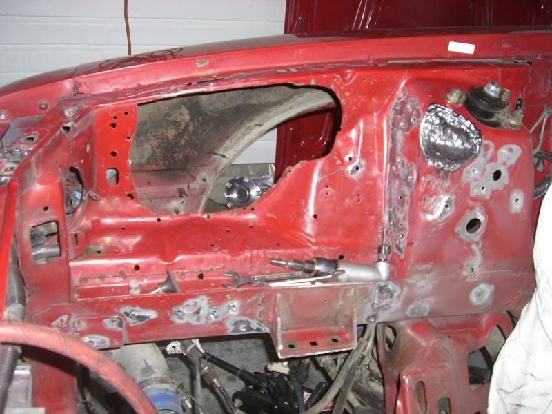
To remove your plastic outer wheel well liners there are just a few screws in the outer fender lip and 1 or 2 that hold the plastic liner in place under the bottom attaching it to the floor panel? There are also a couple of plastic plugs that need to be removed and that�s about it. Then take your hand and hit the plastic liner in an upward motion which should help release the liner, then just pull it out of your way. Some people have removed there fenders for easier access, in my case I didn�t. It�s just that I didn�t want to deal with re aligning of my fenders later is the reason I removed the plastic liner which would have to be removed any way if you remove your fenders. This way I was able to see and access the hole on the back of the Strut Towers to get the connectors and wire through. It also made it easier for me to tie wrap the harness up and out of the way, along with being able to put the solenoid as high as possible on the inside fender, keeping it as high and dry as possible.
Step Two: Wire Time:
All the wires and the harness will fit through the back of the strut tower. You don�t have to remove any wire from any of the connectors. All you need to do is unplug (pull apart) the connector or deal with individual wires that were individual to start with.
First mark both ends of any connector that you�re separating, it will make it easier when you start to put thing back together, a camera is also a big help when it comes time remembering how thing went. Most people seem to forget what wires went where when it comes to the solenoid/ starter relay wires just mark each wire and its location and it will make life easier later.
Next separate the two ends on the different connectors then run the largest connector through the Strut Tower first then followed by the next largest and so on. All the connectors will fit through the hole without having to enlarge the hole in the back of the Strut Tower. It may seem that not all the connectors and wires will fit in to the hole when you first try but with a little finesse everything will go through. It does help if you have someone help you feed the connector and wires through the hole while you pull them through but it�s not necessary.
Now that you have all the wires and connector in the inner fender check where you want to put your solenoid/ starter relay (I found that the farther you go forward with the solenoid/ starter relay and related wires the easier it when you do the other harness such as the headlight harness) making sure all the wires will re attach to the solenoid install the solenoid and then just tie wrap the rest of the harness as high as possible. You will be able to see place on the upper fenders where you can run the tie wraps. Another reason for keeping the harness as high as possible is so when you so when you reinstall the plastic wheel liner they fit like they use to. You can also run your hood release cable through the back of the Strut Tower if you like. If you weld the holes up on the inner fenders, I�d suggest not running your MAF wire harness through the hole in the Strut Tower. You won�t have enough wire to hook it back up without cutting and splicing. Just my $.02
Headlight harness: I also ran my head light and turn signal wire harness on the driver�s side inner fender. The only thing you have to do with the light harness is to make a couple of holes for the ground wire. Just run the light harness in front of the radiator and under the radiator bracket.
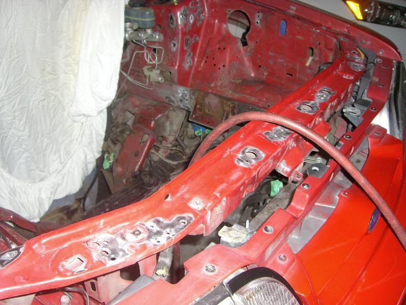
Main Harness: As for the main harness that runs on top of the pinch weld at the fire wall, I found the easiest method to hide this harness was to remove all the old original plastic shielding (which measures almost 1-1/4) and snuggly rewrap the main harness with black electrical tape, which will then make the same main harness less than 7/8 in thickness which can easily be tucked under the pinch weld, basically being hid out of sight.
Side note; As long as you have the old plastic shielding off main harness which expose the wires to the passenger side and drivers side try pulling those wires to the side the wires need to go, either drivers side or passenger side. This helps in lengthening those wires so that later you shouldn�t need to cut and lengthen any wires.
As long as your re routing the main harness too under the pinch weld you can also re route the 2 brake lines that run with the main harness on top of the pinch weld to the underside of the pinch weld by just rolling them under the pinch weld and gently pressing the against the main harness that you just placed under the pinch weld. The brake line also helps hold the main harness tight to the underside of the pinch weld.
Once you�ve got your entire harnesses together and reconnected hook up the battery and start your car to make sure everything works. Next strap the harnesses in place, reinstall the plastic liner etc. etc. if you�re welding up the inner fenders do the welding first, then reroute your wires. If your wonder I only had to cut and splice 2 different set of wire when I re routed my wires. One set to the A/C compressor and the other set to the Overflow bottle. You may also need a longer positive side battery cable depending on where your battery is located and how you want route the battery cable, and possibly longer starter cable again depend now you want to route the starter cable.
Hiding Vacuum Lines
Step Three: Vacuum Lines:
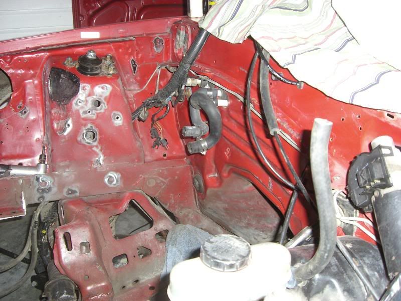
As long as you have the plastic fender off now would be the time to hide the (2) Vacuum tree on the upper fire wall. This can be done by putting the vacuum trees under the fenders, one on each side and running new lines through the hole in the inner fenders. Use the factory hole no need to drill new holes. Take the Large Vacuum Tree (Lettering Left to right) S (source), B/R (capped), A/C (air conditioning) S/C (driver side fender), B/B (brake booster) that on the firewall by the brake booster and put it under the driver side fender close to the Speed Control Module, or up high in the fender well as possible.
All you need to do is extend (2) of the rubber hoses (Manifold, Brake Booster) and shorten the hose that comes from the Speed Control Module (cruise control) which is a black looking ball under the driver�s side fender. The other smaller vacuum module (not sure what is called) that�s on the passenger side upper fire wall close to the hood hinge. I moved to under the passenger side fender. The basic purpose is for vacuum module is for to the A/C.
I bought a package of air shock tubing (hard plastic line use for filling air shocks $10) because I couldn�t find the smaller hard plastic tubing. The air shock tubing has approximately the same inside and outside diameter as the factory plastic tubing and fits snugly on 3/16 wiper tubing (7/32 ID), I also bought approximately 12� of 3/16 rubber wiper tubing. Or you could buy 3/16 (7/32 ID) rubber wiper tubing to do it all. It�s just harder to hide the larger diameter rubber hose under the pinch weld.
I cut the factory hard plastic line leaving approximately 3/8 of the plastic line stick past to the stock rubber boot, I then cut a 3/4 � piece of wiper tubing to couple the 2 ends together. You�ll need some sort of lube (nothing with and oil base) to couple the factory end with rubber boot to the air shock tubing, believe me it�s a snug fit. Take a line (hard plastic or rubber) from the larger vacuum tree that you�ve put under the drivers side fender and run the line from the tree marked as A/C under the pinch weld to the passenger side through the factory hole in the inner fenders and connect it to the smaller vacuum module. Then take another line (hard plastic or rubber) and run it from the vacuum module back through the same hole and under the pinch weld to the vacuum line that comes out beside the heater lines.
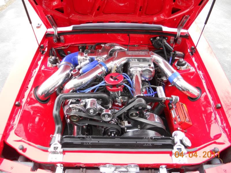
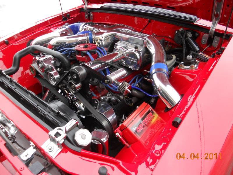
I have a few pictures here that show how I ran those wires that should also be helpful.
http://smg.photobucket.com/albums/v4...Wire%20Hiding/
Disconnect the battery; jack up which side of the car you want to work on (or both sides). Use jack stands or something similar to support the car. Remove the tire and then remove the plastic fender liner.
To remove your plastic outer wheel well liners there are just a few screws in the outer fender lip and 1 or 2 that hold the plastic liner in place under the bottom attaching it to the floor panel? There are also a couple of plastic plugs that need to be removed and that�s about it. Then take your hand and hit the plastic liner in an upward motion which should help release the liner, then just pull it out of your way.
Step one:
The Basics
To remove your plastic outer wheel well liners there are just a few screws in the outer fender lip and 1 or 2 that hold the plastic liner in place under the bottom attaching it to the floor panel? There are also a couple of plastic plugs that need to be removed and that�s about it. Then take your hand and hit the plastic liner in an upward motion which should help release the liner, then just pull it out of your way. Some people have removed there fenders for easier access, in my case I didn�t. It�s just that I didn�t want to deal with re aligning of my fenders later is the reason I removed the plastic liner which would have to be removed any way if you remove your fenders. This way I was able to see and access the hole on the back of the Strut Towers to get the connectors and wire through. It also made it easier for me to tie wrap the harness up and out of the way, along with being able to put the solenoid as high as possible on the inside fender, keeping it as high and dry as possible.
Step Two: Wire Time:
All the wires and the harness will fit through the back of the strut tower. You don�t have to remove any wire from any of the connectors. All you need to do is unplug (pull apart) the connector or deal with individual wires that were individual to start with.
First mark both ends of any connector that you�re separating, it will make it easier when you start to put thing back together, a camera is also a big help when it comes time remembering how thing went. Most people seem to forget what wires went where when it comes to the solenoid/ starter relay wires just mark each wire and its location and it will make life easier later.
Next separate the two ends on the different connectors then run the largest connector through the Strut Tower first then followed by the next largest and so on. All the connectors will fit through the hole without having to enlarge the hole in the back of the Strut Tower. It may seem that not all the connectors and wires will fit in to the hole when you first try but with a little finesse everything will go through. It does help if you have someone help you feed the connector and wires through the hole while you pull them through but it�s not necessary.
Now that you have all the wires and connector in the inner fender check where you want to put your solenoid/ starter relay (I found that the farther you go forward with the solenoid/ starter relay and related wires the easier it when you do the other harness such as the headlight harness) making sure all the wires will re attach to the solenoid install the solenoid and then just tie wrap the rest of the harness as high as possible. You will be able to see place on the upper fenders where you can run the tie wraps. Another reason for keeping the harness as high as possible is so when you so when you reinstall the plastic wheel liner they fit like they use to. You can also run your hood release cable through the back of the Strut Tower if you like. If you weld the holes up on the inner fenders, I�d suggest not running your MAF wire harness through the hole in the Strut Tower. You won�t have enough wire to hook it back up without cutting and splicing. Just my $.02
Headlight harness: I also ran my head light and turn signal wire harness on the driver�s side inner fender. The only thing you have to do with the light harness is to make a couple of holes for the ground wire. Just run the light harness in front of the radiator and under the radiator bracket.
Main Harness: As for the main harness that runs on top of the pinch weld at the fire wall, I found the easiest method to hide this harness was to remove all the old original plastic shielding (which measures almost 1-1/4) and snuggly rewrap the main harness with black electrical tape, which will then make the same main harness less than 7/8 in thickness which can easily be tucked under the pinch weld, basically being hid out of sight.
Side note; As long as you have the old plastic shielding off main harness which expose the wires to the passenger side and drivers side try pulling those wires to the side the wires need to go, either drivers side or passenger side. This helps in lengthening those wires so that later you shouldn�t need to cut and lengthen any wires.
As long as your re routing the main harness too under the pinch weld you can also re route the 2 brake lines that run with the main harness on top of the pinch weld to the underside of the pinch weld by just rolling them under the pinch weld and gently pressing the against the main harness that you just placed under the pinch weld. The brake line also helps hold the main harness tight to the underside of the pinch weld.
Once you�ve got your entire harnesses together and reconnected hook up the battery and start your car to make sure everything works. Next strap the harnesses in place, reinstall the plastic liner etc. etc. if you�re welding up the inner fenders do the welding first, then reroute your wires. If your wonder I only had to cut and splice 2 different set of wire when I re routed my wires. One set to the A/C compressor and the other set to the Overflow bottle. You may also need a longer positive side battery cable depending on where your battery is located and how you want route the battery cable, and possibly longer starter cable again depend now you want to route the starter cable.
Hiding Vacuum Lines
Step Three: Vacuum Lines:
As long as you have the plastic fender off now would be the time to hide the (2) Vacuum tree on the upper fire wall. This can be done by putting the vacuum trees under the fenders, one on each side and running new lines through the hole in the inner fenders. Use the factory hole no need to drill new holes. Take the Large Vacuum Tree (Lettering Left to right) S (source), B/R (capped), A/C (air conditioning) S/C (driver side fender), B/B (brake booster) that on the firewall by the brake booster and put it under the driver side fender close to the Speed Control Module, or up high in the fender well as possible.
All you need to do is extend (2) of the rubber hoses (Manifold, Brake Booster) and shorten the hose that comes from the Speed Control Module (cruise control) which is a black looking ball under the driver�s side fender. The other smaller vacuum module (not sure what is called) that�s on the passenger side upper fire wall close to the hood hinge. I moved to under the passenger side fender. The basic purpose is for vacuum module is for to the A/C.
I bought a package of air shock tubing (hard plastic line use for filling air shocks $10) because I couldn�t find the smaller hard plastic tubing. The air shock tubing has approximately the same inside and outside diameter as the factory plastic tubing and fits snugly on 3/16 wiper tubing (7/32 ID), I also bought approximately 12� of 3/16 rubber wiper tubing. Or you could buy 3/16 (7/32 ID) rubber wiper tubing to do it all. It�s just harder to hide the larger diameter rubber hose under the pinch weld.
I cut the factory hard plastic line leaving approximately 3/8 of the plastic line stick past to the stock rubber boot, I then cut a 3/4 � piece of wiper tubing to couple the 2 ends together. You�ll need some sort of lube (nothing with and oil base) to couple the factory end with rubber boot to the air shock tubing, believe me it�s a snug fit. Take a line (hard plastic or rubber) from the larger vacuum tree that you�ve put under the drivers side fender and run the line from the tree marked as A/C under the pinch weld to the passenger side through the factory hole in the inner fenders and connect it to the smaller vacuum module. Then take another line (hard plastic or rubber) and run it from the vacuum module back through the same hole and under the pinch weld to the vacuum line that comes out beside the heater lines.
I have a few pictures here that show how I ran those wires that should also be helpful.
http://smg.photobucket.com/albums/v4...Wire%20Hiding/
 07-26-2011, 02:56 AM
#67
Sorry I didn't even look lol. Is it pretty easy or is it hard? I know it takes time and patience but as far as the re-routing goes it sounds hard. Right now would probably be a good time to do it since my engine is torn apart at the moment. Do you have to pull the whole engine out to do it?

 03-17-2012, 10:13 PM
#70

Join Date: Mar 2012
Location: GA
Posts: 3
I know this is an old thread but I'm new to the sight and cant pm anyone yet. If you see this Almost Stock can you please send me your write up with pics to dargo72@hotmail.com . Especially pics of where you mounted everthing and how you ran the wires that you need in the bay back in. Your car looks awesome. Also I wanted to bump what I think is a awesome thread.

