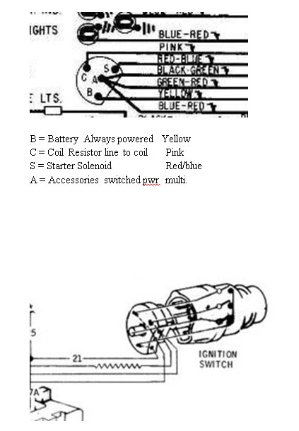
Schematic/Diagram for 69 Ignition Switch
#1
Need a 12v source hopefully inside the interior already for "only 12v when ignition on". Ignition switch is the only thing I can think of, and I can't find a schematic or diagram of it in the factory manuals?? Or can I splice into a gauge circuit somewhere? Where? I think I remember reading the gauges run on fewer than 12 volts.
Lights are separate, accessories are on Accessory. I am hooking up a tach. This is not for the light bulb in the tach to be clear. Or do people run a wire from the engine bay through a grommet in the firewall for a 12v ignition source.
Lights are separate, accessories are on Accessory. I am hooking up a tach. This is not for the light bulb in the tach to be clear. Or do people run a wire from the engine bay through a grommet in the firewall for a 12v ignition source.
#2
The one thing these cars lack is a 12v switched source. See if my memory is worth a crap. Go pick up a four pin relay, fuse, and a four or eight circuit fuse block. connect the relay switch side to your ign source (86), and run the relay dedicated power side to 12V battery (30) with the inline fuse. run the relay power output to the fuse block (87). add ground (85). If its like my 66 the lug nut on the end of the ign switch is a 12V ign source. If you use the 4 circuit ATO type fuse block, one side of the block is one long bus so you only need to wire once for the switched power source to the fuse block. You will then have 12V switched on all the fuse block circuits without overloading your ign switch. You can place that fuse block anywhere you want. The biggest headache is running the dedicated 12V to the relay through the firewall. I personally have one fuse block that is all 12V switched and one fuse block that is 12V dedicated power in my 66.
Last edited by groho; 04-06-2017 at 12:26 PM.
#3
I tested the ignition switch today to see which terminals get switched 12v, and I will admit I spliced into a pinkish peach color wire that I found there. According to the gauge instructions it pulls a max of 4 amps (which I don't think is even possible) so I think it will be ok. I will put an line fuse on this wire to protect the gauge, but otherwise I don't see what could go wrong really. The wire I tapped into is a pretty large size too, which makes me think it will be safe.
I will admit this would be a good time to run a 12v switched source into the cabin. I know what I did isn't ideal, but I don't plan on further interior electrical changes anytime soon so I don't think I will be overloading the wire I used.
I will admit this would be a good time to run a 12v switched source into the cabin. I know what I did isn't ideal, but I don't plan on further interior electrical changes anytime soon so I don't think I will be overloading the wire I used.
#5
I tested the ignition switch today to see which terminals get switched 12v, and I will admit I spliced into a pinkish peach color wire that I found there. According to the gauge instructions it pulls a max of 4 amps (which I don't think is even possible) so I think it will be ok. I will put an line fuse on this wire to protect the gauge, but otherwise I don't see what could go wrong really. The wire I tapped into is a pretty large size too, which makes me think it will be safe.
I will admit this would be a good time to run a 12v switched source into the cabin. I know what I did isn't ideal, but I don't plan on further interior electrical changes anytime soon so I don't think I will be overloading the wire I used.
I will admit this would be a good time to run a 12v switched source into the cabin. I know what I did isn't ideal, but I don't plan on further interior electrical changes anytime soon so I don't think I will be overloading the wire I used.
#6
I'm rethinking that it would be a great idea to add a small fuse block for switched 12v inside the car. I think I will do this. Later on i could see this being helpful. I am assuming the pink wire I spliced into would be fine as a trigger wire for a relay. Luckily I left extra length on it.
First thing I did was check the fuse block for an extra port but saw nothing.
First thing I did was check the fuse block for an extra port but saw nothing.


