How to install a fuel pressure gauge?

 01-10-2013, 01:56 PM
#12
4th Gear Member

Join Date: Jun 2006
Location:
Posts: 1,227
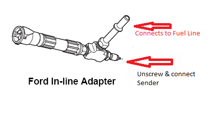
No it does not. you unclip the line and insert the adapter between the two ends just disconnected. Remove the nipple from the block and install your sending unit. (easier to install the sender on the workbench before inserting the line)
You will need to ground the sending unit since the lines are neoprene.
You will need to ground the sending unit since the lines are neoprene.
01-11-2013, 08:39 PM
#13
2nd Gear Member
Join Date: Feb 2009
Location: FL
Posts: 453
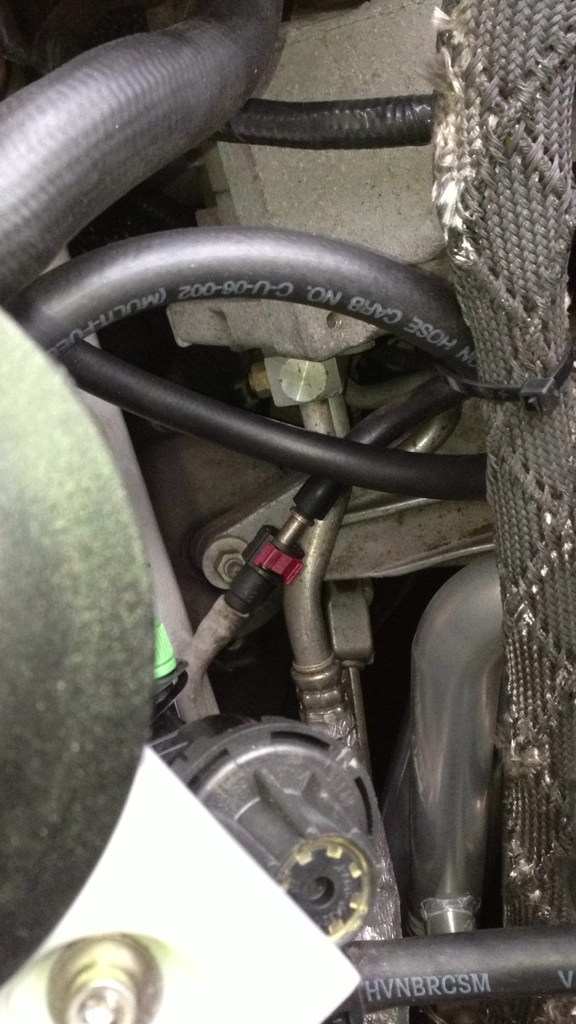
Is the tube with the red latch the correct one? Do I depressurize the fuel system like I did when I swapped in my new injectors? After dislodging the clip should I expect fuel to leak out? Sorry...still a noob lol
01-12-2013, 12:21 PM
#15
2nd Gear Member
Join Date: Feb 2009
Location: FL
Posts: 453
Great, thanks for the added info! My sender/adapter kit for the Aeroforce should be here next week, along with the hose adapter from Toolsource.com. I'll probably be attempting my gauge install next weekend as my boost gauge and vent pods arrived yesterday.
01-16-2013, 09:55 AM
#16
2nd Gear Member
Join Date: Feb 2009
Location: FL
Posts: 453

Ok, so I got the piece in and have another question or two...sorry I'm still such a noob, but with this being the fuel system I want to be sure I don't make any mistakes.
This is the piece I received:

Earlier posts mentioned removing the brass nipple part that sticks out of the side. I tried to see if it would move with light pressure from a wrench and it didn't want to come off, so I wanted to be sure that this is the case(removal of the brass 'nipple'. One end is brass and looks like what a valve stem on a tire looks like so I'm guessing this is where the sender screws in? The other end is open with a small plastic clip in it. It looks like that end is shown in your pic, but the other end of the fuel line with the red connector connects where? Does it connect to the side after the nipple is removed? Does the small plastic clip stay in and secure the fuel line? I'm still a little puzzled on how this connects this into my fuel line. I'm sorry to ask so many questions, but I just want to know before I start disconnecting things this weekend. maybe it will be easier once I get started, but I just wanted to be sure....maybe a pic showing more would help (if that's possible).
01-16-2013, 08:43 PM
#17
4th Gear Member
Join Date: Jun 2006
Location:
Posts: 1,227
The nipple is the brass fitting opposite the hose. (top fitting in the picture) Replace it with the sensor (use teflon tape to seal)
The long brass pipe connects to the hose on the car you disconnected and the rubber hose on the adapter connects to where that existing hose did.
The long brass pipe connects to the hose on the car you disconnected and the rubber hose on the adapter connects to where that existing hose did.
01-16-2013, 11:30 PM
#18
2nd Gear Member
Join Date: Feb 2009
Location: FL
Posts: 453
I apparently missed this pic/post. 
Now from what you just said the sender screws onto the top of the whole assembly. I remove the brass pipe that is bolted into the brass fitting and install one end of the fuel line there and the other end into the end of the hose and that end also gets secured by the white plastic clip. Is that correct, or is the entire brass fitting the nipple...I promise I'm not as stupid as these posts make me out to be lol.

In this pic it says to remove the brass pipe that is attached to the fitting and that is where the sender goes, but in the actual pic you posted it looks like the sender is attached to the top of the brass section. So what goes where...the sender at the top and the brass pipe removed and replaced with the fuel line coupler with the red clasp? In your most recent post it reads like the brass pipe doesn't get disconnected, but instead connects to the red clasp side of the fuel line. Maybe it'll all make sense when I have the sending unit in my hands on Friday, I'm just trying to get this straight from drawings. In my daytime hours I make technical drawings as part of my engineering plans that I write, but looking over these pics and diagrams has me feeling awful stupid lol.
Now from what you just said the sender screws onto the top of the whole assembly. I remove the brass pipe that is bolted into the brass fitting and install one end of the fuel line there and the other end into the end of the hose and that end also gets secured by the white plastic clip. Is that correct, or is the entire brass fitting the nipple...I promise I'm not as stupid as these posts make me out to be lol.
In this pic it says to remove the brass pipe that is attached to the fitting and that is where the sender goes, but in the actual pic you posted it looks like the sender is attached to the top of the brass section. So what goes where...the sender at the top and the brass pipe removed and replaced with the fuel line coupler with the red clasp? In your most recent post it reads like the brass pipe doesn't get disconnected, but instead connects to the red clasp side of the fuel line. Maybe it'll all make sense when I have the sending unit in my hands on Friday, I'm just trying to get this straight from drawings. In my daytime hours I make technical drawings as part of my engineering plans that I write, but looking over these pics and diagrams has me feeling awful stupid lol.
Last edited by Topless Stang; 01-16-2013 at 11:46 PM.
01-17-2013, 11:33 AM
#19
4th Gear Member
Join Date: Jun 2006
Location:
Posts: 1,227
I apparently missed this pic/post.
Now from what you just said the sender screws onto the top of the whole assembly. I remove the brass pipe that is bolted into the brass fitting and install one end of the fuel line there and the other end into the end of the hose and that end also gets secured by the white plastic clip. Is that correct, or is the entire brass fitting the nipple...I promise I'm not as stupid as these posts make me out to be lol.
In this pic it says to remove the brass pipe that is attached to the fitting and that is where the sender goes, but in the actual pic you posted it looks like the sender is attached to the top of the brass section. So what goes where...the sender at the top and the brass pipe removed and replaced with the fuel line coupler with the red clasp? In your most recent post it reads like the brass pipe doesn't get disconnected, but instead connects to the red clasp side of the fuel line. Maybe it'll all make sense when I have the sending unit in my hands on Friday, I'm just trying to get this straight from drawings. In my daytime hours I make technical drawings as part of my engineering plans that I write, but looking over these pics and diagrams has me feeling awful stupid lol.
Honestly, if you walk to the car and look at the existing hose and the adapter hose, it's pretty obvious how the adapter hose is installed and where the sender would go.
01-17-2013, 11:42 AM
#20
2nd Gear Member
Join Date: Feb 2009
Location: FL
Posts: 453
Ok, I think I got it. I did a crude mock up in MS Paint...is this right? I'm sorry, I don't have the sender in yet, just the hose & I want to be sure how everything connects together. It would probably have been much easier if I waited until tomorrow when I have the sender in my hands...