Ford Mustang GT 1996-2004: How to Install 2-Step Launch Control
A 2-Step launch controller disables the ignition enough to allow the engine RPM's to remain at a constant level. This frees up the driver's focus that would otherwise be used to keep the accelerator pedal positioned correctly for an optimal launch.
This article applies to the Ford Mustang GT (1996-2004).
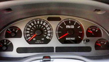
2-Step launch control allows the driver to reduce their 60 ft. times at the drag strip by dialing in the launch RPM within 100 RPM increments. When you're crossing the 1320, a mere 60' may seem insignificant, but the 60' indicates how effectively a car can put the power to the ground. Rough math dictates that every tenth of a second dropped in your 60' times are good for 0.2 to 0.3 of a second over the 1/4 mile, which is huge.
Launch control is great for making adjustments to new modifications, weather conditions, and tire pressures. Another great feature useful for owners with forced induction setups is the ability to build boost at the starting line. Depending on your launch, RPM boost can be built over five psi, creating zero turbo lag, which means the car lands in the torque band, right off the line.
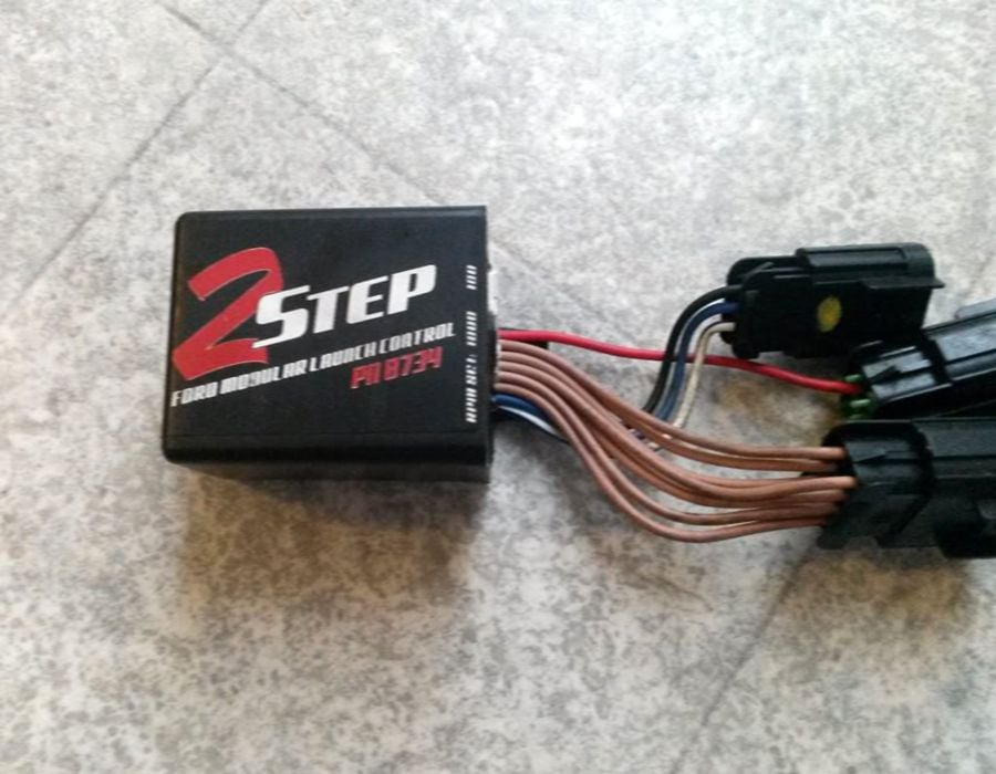
The MSD 2-Step system uses a custom made harness that is almost completely plug and play. It is advised not to use the 2-Step for longer than five seconds at one time, as damage to the catalytic converters can result. This also creates extreme levels of heat inside the engine. With all of that covered, here's the basics on getting your 2-Step installed.
Materials Needed
- Socket set (8mm-15mm)
- 1/4" and 3/8" ratchet
- Flat head screwdriver
- Electric drill
- Wiring crimper
Step 1 – Mount the 2-Step control box
You will want to mount the box away from heat sources and near areas where wiring connects. On the firewall is a good location. Use a drill to mount the box with the self-tapping screws.
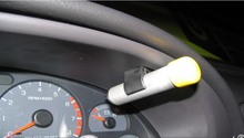
Step 2 – Connect the black wire to a good ground
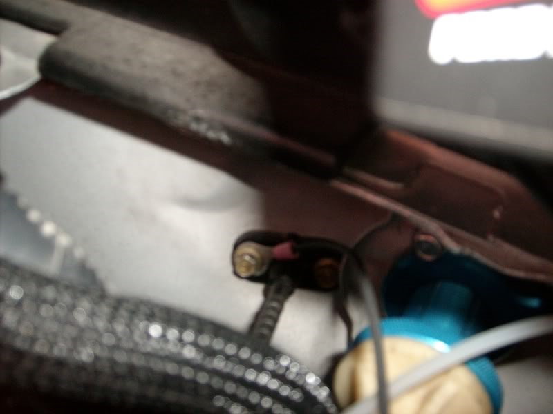
Mount this wire to a good ground on the vehicle body. One forum user mounted his ground wire to the firewall, where the throttle body cable passes through (as seen in Figure 2). Also, connect the 3-pin connector to the 2-Step control box.
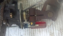
Step 3 – Disconnect the ignition coil electrical connectors
The ignition coils are mounted on top of the valve covers near the fuel rails. You may need to remove the intake tubing on the passenger's side of the engine to access those four coils. Loosen the metal clamps on each end of the piping with a flat head screwdriver and disconnect the electrical connector from the sensor near the mass air flow meter. Remove the rubber air hoses from the intake pipe, as well.
Squeeze the flexible tab on the ignition coil's electrical connectors while pulling them away from the coils to separate the two.

Step 4 – Connect ignition coil to 2-Step wiring harness
Connect the ignition coil's electrical connectors to the 2-Step wiring harness. These connectors simply snap together. Route the wiring along the existing wiring for a clean install.
Step 5 – Check status on the 2-Step
Check the status on the 2-Step control box using the LED. First, connect the 8-pin electrical connector with the single red wire from the 2-Step to the connector with black wires.
Check the status by turning the ignition to the on position. If the LED on the 2-Step box stays lit, the wiring is harness is correctly installed. If the LED does not illuminate, turn the ignition off and plug the 8-pin electrical connector with the gray wires to the connector with the single red wire.
Step 6 – Connect the remaining harness connections
First connect the 8-pin electrical connector with the tan wires to the remaining open harness. Also, connect the 2-pin electrical connectors from the MSD harness to the factory coil packs.
Step 7 – Connect the activation wire
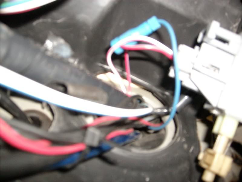
The activation wire can be connected to ground or to a 12 volt source. A commonly used 12 volt source is the clutch position switch. If you choose to wire it to ground, a switch must be used that will allow manual activation.
When using the clutch position switch, connect the blue/white wire from the 3-pin electrical connector to the switch.
Splice the wires together using the provided materials and a crimping tool.
Step 8 – Verify the installation is correct
With the engine running, activate the 2-Step on/off switch. The LED should illuminate when the switch is activated. Set the RPM to a low limit and test for proper operation. The result should be similar to the video below.
Featured Video: Mustang GT 4.6L 2-Step
Related Discussions
- MSD 2-Step Install with Pics - MustangForums.com
- Anybody Install 2-Step - MustangForums.com
- MSD 2-Step Launch Controller - MustangForums.com
- 2 Step Launch Control - MustangForums.com
- 2-Step Launch Control Worth It - MustangForums.com