
HOW TO: Install Dual Solenoid Line Locks
 03-06-2008, 01:45 PM
#1
MF Administrator
Thread Starter
Join Date: May 2005
Location: South Carolina
Posts: 8,191
This How-To thread is being written to show the steps I took to install a dual solenoid line lock (or roll control) system on my 2006 4.0L V6 Pony Package coupe. The car has anti-lock brakes (ABS), so I followed the advice of others and went with a dual solenoid system. Some have posted that a single solenoid will suffice on cars with ABS, but I decided to take the recommendation of the majority who have weighed in on the subject.
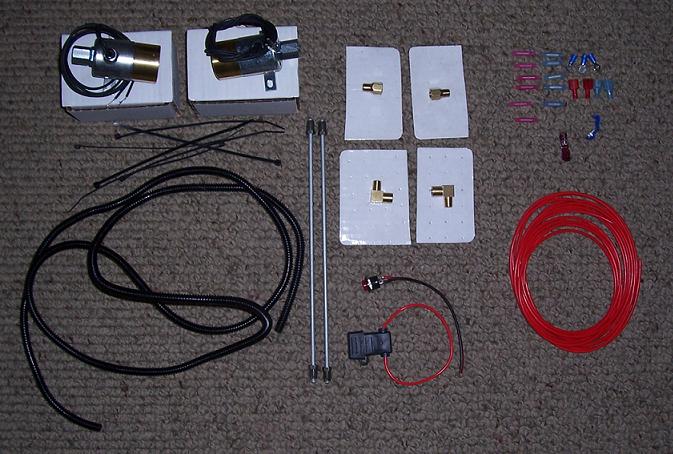
The system I purchased was a "kit" from PowerHouse Automotive (PH). I use the term kit loosely, because it is really a combination of parts amassed by PH. The solenoids are from Biondo Racing, and the rest of the components could be purchased by a self-installer, if you so desired to gather the needed parts yourself. The procedure outlined below could also be used as a general guide if you purchase a kit by another supplier, or wanted to installline locks on a different vehicle.
Below is a picture of what came with the PH "kit":
MOUNTING THE SOLENOIDS
Although I mounted the solenoids after[/i] running most of the wiring first, listing the solenoids first will make it easier to explain the installation.
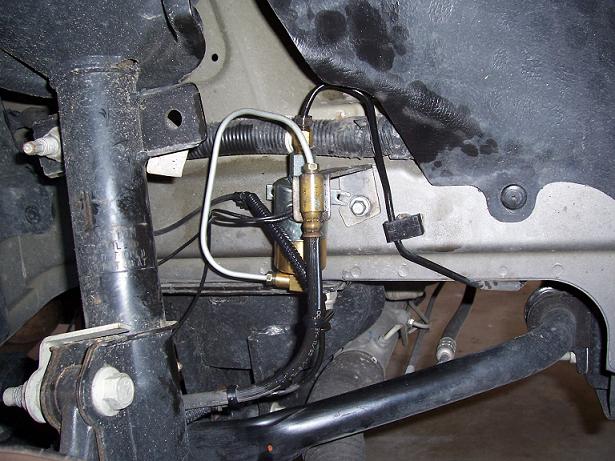
An installation diagram was supplied with the solenoids. For these parts, the nutted side of the solenoid connects to the feed line from the master cylinder. The brass side of the solenoid goes to the brakes (brass-to-brakes). I used the brass fittings supplied by PH, and attached them to the solenoid while securely in a vise. It's a lot better to work on them at your workbench rather than inside the wheelwell. Make sure your connections are TIGHT, but don't strip out the brass fittings either. Pipe dope is available that is OK to use with oil based liquids, but I kept my fittings dry. In my case, I mounted the 90* fitting on the brake side of the solenoid.
Rather than try to mount the solenoids under the hood, I mounted them in the wheelwells right next to the bracket where the hardline meets the flexible brake line. In fact, I used the guide pin for the bracket as one of the mounting points for each solenoid.

For the other side of the solenoid, I drilled a hole and secured it with a sheet metal screw. When running the ground wire, you can either secure the wire to this screw, or to the bolt that holds the brake line bracket (as in the above photo).
I mounted the solenoids in such a way that the hardline could be "gently motivated" to fit inside the straight brass fitting I attached to the solenoid. Once that it tightened, I needed to route a hard line from the 90* fitting on the solenoid to the fitting for the flex line held by the brake line bracket. Taking the 12" steel line supplied by PH, I used my trusty tube bender to create the custom line necessary for each side.

Although I had envisioned creating beautiful 90* bends for a highly professional look, my measuring was off and the bends were not always in the exact spot they should have been. Still, it looks OK (nobody will see it unless the tire is removed), and it works fine despite how it looks.

Thoroughly bleed the brakes (passenger side, then driver's side). Check for leaks by having someone apply the brakes while you check each side. Retighten your fittings as necessary.
WIRING
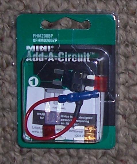
Rather than use the 5 amp in-line fuse PH supplied, I went to Pep Boys and purchased a cool little item called Add-A-Circuit. It uses the mini-fuses, and is an easy way to supply power to low amp accessories.
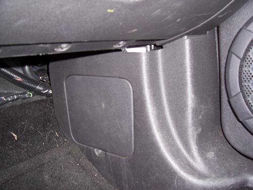
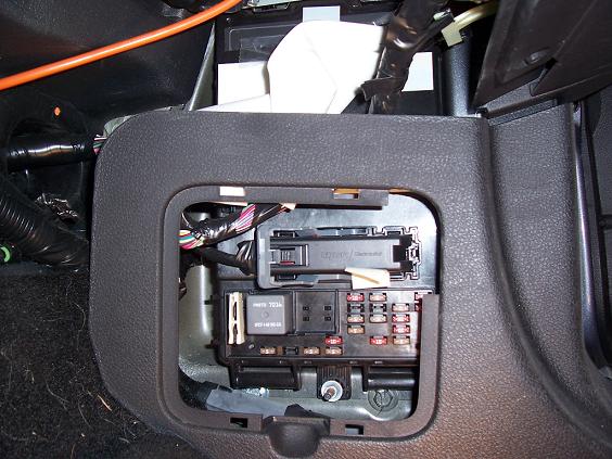
For those who don't know, there is a fuse panel inside the car, which is located in the footwell on the passenger side of the car.
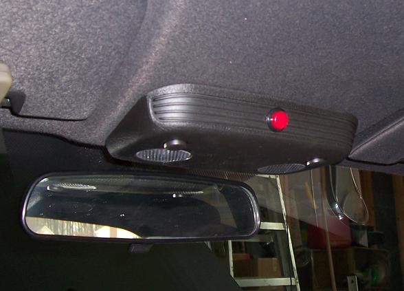
Before I talk about running the wires, I should comment about switch location. You can mount your switch wherever you like. I know some have mounted a pole switch to the wire that controls the high beams or the windshield washer. With the flip of a remote switch, that puts the control for the linelocks at finger distance from the wheel. That's awfully convenient, but you'll have to look elsewhere to determine which wire to use. I wanted to keep the install simple, and decided that I wanted the switch out of the way, so I mounted it in the upper console by the overhead interior lights. The panel pulls down with a little bit of effort.
I drilled a hole in the front of the panel, and attached the switch to the panel. Here's a shot I took once the wiring was complete:
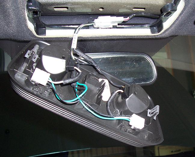
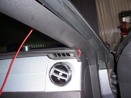
I fished two wires through the opening behind the console, and ran them along the windshield behind the headliner towards the passenger side of the car. The inside cover for the A-pillar pulls down with a gentle tug, and I was able to fish the wires behind the cover to the dash. There is a small opening at the dash where it meets the A-pillar, and I fished the wires through there.
You can fully open your glove box by folding the box inwards and pulling the door towards you; this creates easy access behind the dash. Once the wires were fished, I went back to the switch and connected the wires to the two lines coming off the switch. If you solder your connections, that will make for an even better connection.
Going back to the wires just fished behind the dash, I used plenty of nylon wire ties and routed the one wire to the fuse panel in the passenger footwell (but did NOT connect it yet). I ran the other wire along the firewall, under the stereo, and behind the driver's side footwell along the firewall towards the driver's side A-pillar behind the dash.
At that point, my wiring supplied with the kit ran out, which created a perfect location for a connection.
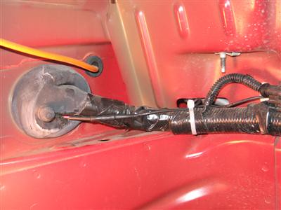
From the solenoids, I used the conduit supplied by PH to shield the power supply wire from the solenoid through the opening in the chassis.

[size=2]I started with the driver's side wiring. The wire from the solenoid isn't very long, so I made a connection with the same gauge wire, and routed it towards the back driver's side corner of the firewall (using plenty of nylon wire ties). To get the power supply line inside to my wire from the switch, I routed it from the engine compartment along a line that goes through a rubber grommet in that back corner. Carefully using an awl, I cleared a way for the wire to go through.

If you can find a better location to take the wire through the firewall, then use it. I ran plenty of wire behind the dash, and used a crimp connector to mate it to the first wire from the switch.
On the passenger side solenoid, I connected another wire to the one fished through the chassis, and used the remaining conduit to route the wire along the back edge of the firewall (remember, nylon wire ties make for a cleaner installation).

Using crimp connectors, I spliced that wire onto the first wire in that back corner.

Now I was ready to connect my Add-A-Circuit to the fuse box.
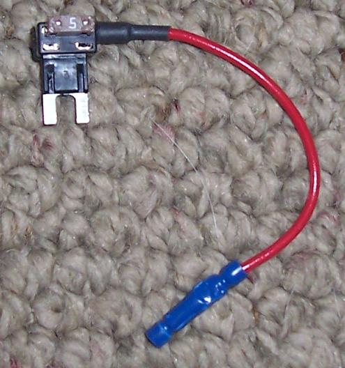
The Add-A-Circuit plugs into an existing fuse location. The head has two fuse slots - one to replace the fuse where you will be plugging it in, and the other for the new circuit. I picked an existing 5 amp slot to plug in the new circuit. Once it is plugged into the fuse panel, the system is ready to use.
Here are a few tips to help you with your installation:
It’s always a good idea to disconnect the battery when working on your car’s electrical system. Before you do that, I suggest that you remember to run your power seat back all the way, and lower your windows.
Running the front seat backwards all the way creates more interior space to work in, and the doors will shut properly if the windows are down and the power is off. It just makes things a little easier.
Use quality jack-stands to support the car while working on it.
The only non-standard tool needed is the tube bender, but they are fairly cheap. Just remember – every project is an excuse to buy new tools!
Another choice would be to use braided steel lines for the connections.
Have a friend help you bleed the brakes - avoid using those junkie vacuum tools to draw the fluid through. Also, I attached a rubber hose to the bleeder, and let it drain into an old shirt – that way it didn’t spray brake fluid all over. Don’t get brake fluid on any painted surfaces you care about.
The way the system works, the solenoids are controlled by a “momentary switch”. That means the solenoids only hold brake pressure while you hold the button. At first, I thought my system wasn’t working because I was pressing and releasing the button like an on/off switch. Pump and hold your brake pedal, then press and hold your switch/button. Once you take your foot off the pedal, the front brakes will remain locked until you take your finger off the switch/button.
Best of luck to you!
The system I purchased was a "kit" from PowerHouse Automotive (PH). I use the term kit loosely, because it is really a combination of parts amassed by PH. The solenoids are from Biondo Racing, and the rest of the components could be purchased by a self-installer, if you so desired to gather the needed parts yourself. The procedure outlined below could also be used as a general guide if you purchase a kit by another supplier, or wanted to installline locks on a different vehicle.
Below is a picture of what came with the PH "kit":
MOUNTING THE SOLENOIDS
Although I mounted the solenoids after[/i] running most of the wiring first, listing the solenoids first will make it easier to explain the installation.
An installation diagram was supplied with the solenoids. For these parts, the nutted side of the solenoid connects to the feed line from the master cylinder. The brass side of the solenoid goes to the brakes (brass-to-brakes). I used the brass fittings supplied by PH, and attached them to the solenoid while securely in a vise. It's a lot better to work on them at your workbench rather than inside the wheelwell. Make sure your connections are TIGHT, but don't strip out the brass fittings either. Pipe dope is available that is OK to use with oil based liquids, but I kept my fittings dry. In my case, I mounted the 90* fitting on the brake side of the solenoid.
Rather than try to mount the solenoids under the hood, I mounted them in the wheelwells right next to the bracket where the hardline meets the flexible brake line. In fact, I used the guide pin for the bracket as one of the mounting points for each solenoid.
For the other side of the solenoid, I drilled a hole and secured it with a sheet metal screw. When running the ground wire, you can either secure the wire to this screw, or to the bolt that holds the brake line bracket (as in the above photo).
I mounted the solenoids in such a way that the hardline could be "gently motivated" to fit inside the straight brass fitting I attached to the solenoid. Once that it tightened, I needed to route a hard line from the 90* fitting on the solenoid to the fitting for the flex line held by the brake line bracket. Taking the 12" steel line supplied by PH, I used my trusty tube bender to create the custom line necessary for each side.
Although I had envisioned creating beautiful 90* bends for a highly professional look, my measuring was off and the bends were not always in the exact spot they should have been. Still, it looks OK (nobody will see it unless the tire is removed), and it works fine despite how it looks.
Thoroughly bleed the brakes (passenger side, then driver's side). Check for leaks by having someone apply the brakes while you check each side. Retighten your fittings as necessary.
WIRING
Rather than use the 5 amp in-line fuse PH supplied, I went to Pep Boys and purchased a cool little item called Add-A-Circuit. It uses the mini-fuses, and is an easy way to supply power to low amp accessories.
For those who don't know, there is a fuse panel inside the car, which is located in the footwell on the passenger side of the car.
Before I talk about running the wires, I should comment about switch location. You can mount your switch wherever you like. I know some have mounted a pole switch to the wire that controls the high beams or the windshield washer. With the flip of a remote switch, that puts the control for the linelocks at finger distance from the wheel. That's awfully convenient, but you'll have to look elsewhere to determine which wire to use. I wanted to keep the install simple, and decided that I wanted the switch out of the way, so I mounted it in the upper console by the overhead interior lights. The panel pulls down with a little bit of effort.
I drilled a hole in the front of the panel, and attached the switch to the panel. Here's a shot I took once the wiring was complete:
I fished two wires through the opening behind the console, and ran them along the windshield behind the headliner towards the passenger side of the car. The inside cover for the A-pillar pulls down with a gentle tug, and I was able to fish the wires behind the cover to the dash. There is a small opening at the dash where it meets the A-pillar, and I fished the wires through there.
You can fully open your glove box by folding the box inwards and pulling the door towards you; this creates easy access behind the dash. Once the wires were fished, I went back to the switch and connected the wires to the two lines coming off the switch. If you solder your connections, that will make for an even better connection.
Going back to the wires just fished behind the dash, I used plenty of nylon wire ties and routed the one wire to the fuse panel in the passenger footwell (but did NOT connect it yet). I ran the other wire along the firewall, under the stereo, and behind the driver's side footwell along the firewall towards the driver's side A-pillar behind the dash.
At that point, my wiring supplied with the kit ran out, which created a perfect location for a connection.
From the solenoids, I used the conduit supplied by PH to shield the power supply wire from the solenoid through the opening in the chassis.
[size=2]I started with the driver's side wiring. The wire from the solenoid isn't very long, so I made a connection with the same gauge wire, and routed it towards the back driver's side corner of the firewall (using plenty of nylon wire ties). To get the power supply line inside to my wire from the switch, I routed it from the engine compartment along a line that goes through a rubber grommet in that back corner. Carefully using an awl, I cleared a way for the wire to go through.
If you can find a better location to take the wire through the firewall, then use it. I ran plenty of wire behind the dash, and used a crimp connector to mate it to the first wire from the switch.
On the passenger side solenoid, I connected another wire to the one fished through the chassis, and used the remaining conduit to route the wire along the back edge of the firewall (remember, nylon wire ties make for a cleaner installation).
Using crimp connectors, I spliced that wire onto the first wire in that back corner.
Now I was ready to connect my Add-A-Circuit to the fuse box.
The Add-A-Circuit plugs into an existing fuse location. The head has two fuse slots - one to replace the fuse where you will be plugging it in, and the other for the new circuit. I picked an existing 5 amp slot to plug in the new circuit. Once it is plugged into the fuse panel, the system is ready to use.
Here are a few tips to help you with your installation:
It’s always a good idea to disconnect the battery when working on your car’s electrical system. Before you do that, I suggest that you remember to run your power seat back all the way, and lower your windows.
Running the front seat backwards all the way creates more interior space to work in, and the doors will shut properly if the windows are down and the power is off. It just makes things a little easier.
Use quality jack-stands to support the car while working on it.
The only non-standard tool needed is the tube bender, but they are fairly cheap. Just remember – every project is an excuse to buy new tools!
Another choice would be to use braided steel lines for the connections.
Have a friend help you bleed the brakes - avoid using those junkie vacuum tools to draw the fluid through. Also, I attached a rubber hose to the bleeder, and let it drain into an old shirt – that way it didn’t spray brake fluid all over. Don’t get brake fluid on any painted surfaces you care about.
The way the system works, the solenoids are controlled by a “momentary switch”. That means the solenoids only hold brake pressure while you hold the button. At first, I thought my system wasn’t working because I was pressing and releasing the button like an on/off switch. Pump and hold your brake pedal, then press and hold your switch/button. Once you take your foot off the pedal, the front brakes will remain locked until you take your finger off the switch/button.
Best of luck to you!

 03-06-2008, 09:13 PM
#4
4th Gear Member
Join Date: Jul 2007
Location: East Moline, IL
Posts: 1,852
Nice job. I used a rocker switch so that I could shift to second. I know they recommend a momentary switch, but you gotta do what's convenient for you 
For anyone interested, I just recently did one for GT's with the PMP kit.
http://www.stangnet.com/Tech-Article...ll-080225.html
For anyone interested, I just recently did one for GT's with the PMP kit.
http://www.stangnet.com/Tech-Article...ll-080225.html


 03-10-2008, 09:13 PM
#10
4th Gear Member
Join Date: Jul 2007
Location: East Moline, IL
Posts: 1,852
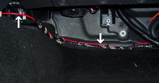
For anyone looking for a different way to run the wiring from the solenoids, you can take the rear wheel well cover off and there's a huge grommet behind it that comes into the cabin. There's one on each side, so it works perfectly. I just poked a hole in that. It worked perfectly. Here's a few pics of it, again from my GT write-up on StangNet.
For reference, here's the whole write-up with larger pictures:
http://www.stangnet.com/Tech-Article...ll-080225.html
For reference, here's the whole write-up with larger pictures:
http://www.stangnet.com/Tech-Article...ll-080225.html

Thread
Thread Starter
Forum
Replies
Last Post