someone who knows electronics i need help!
 08-16-2012, 10:54 PM
#1
Thread Starter

Join Date: Jul 2012
Location: CA
Posts: 28
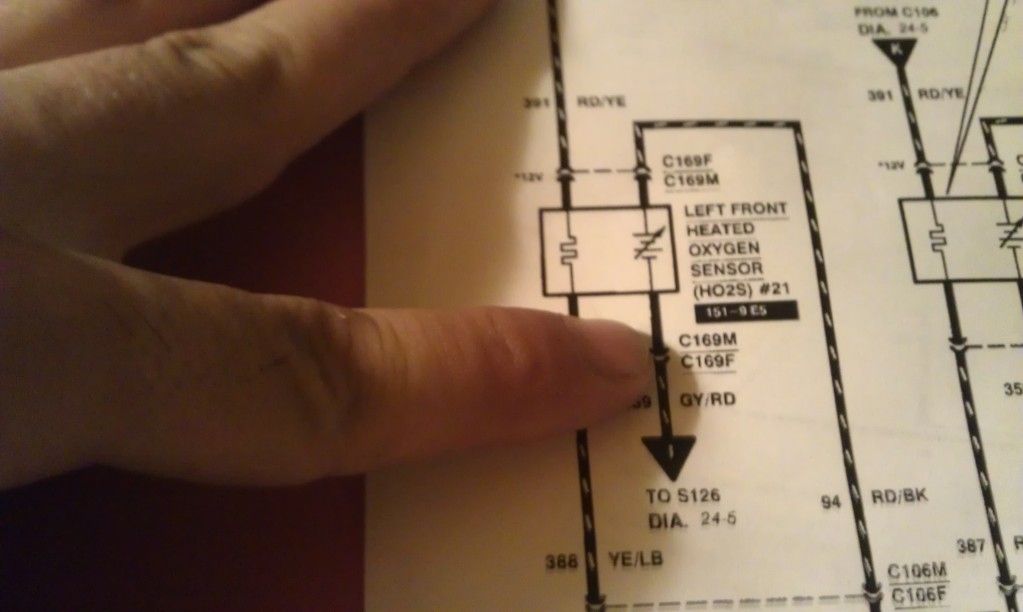
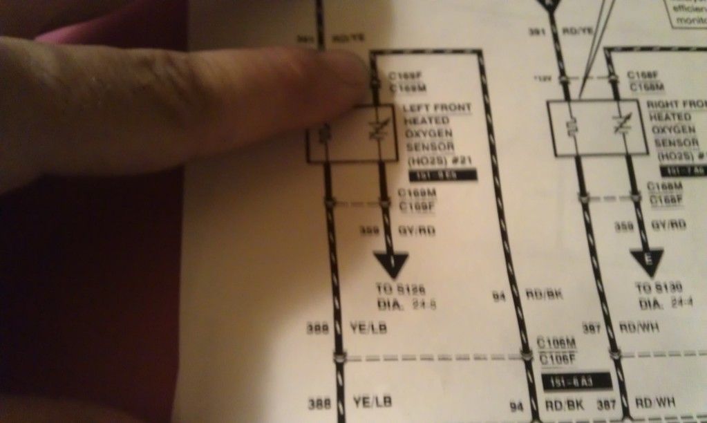
i may not be the sharpest tool in the shed but i am pretty good at poking and testing around on things when it comes to cars. today i have been chasing a short (or at least i believe it may be) in my o2 sensor wiring. i have a p1131 and using my live link i can see that my passenger side B1 front o2 sensor is reading nothing. i checked all the connections to the ecu and they are all good. however when i check the wiring to the o2 sensor connector i am getting a little suspicious. on my drivers side front o2 sensor it reads 12v from where its supposed to get 12v from heres a picture of the wiring diagram where i am getting this reading. and this sensor works just fine.
and heres where it connects to the pcm and gets a 0v reading and is functioning properly. i believe this is either grounded in the pcm or it sends a reading to the pcm.
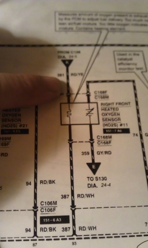
OK... on the passenger side i get a 12v reading when i ground my meter both
here which is the one i suspect shouldnt be 12v)
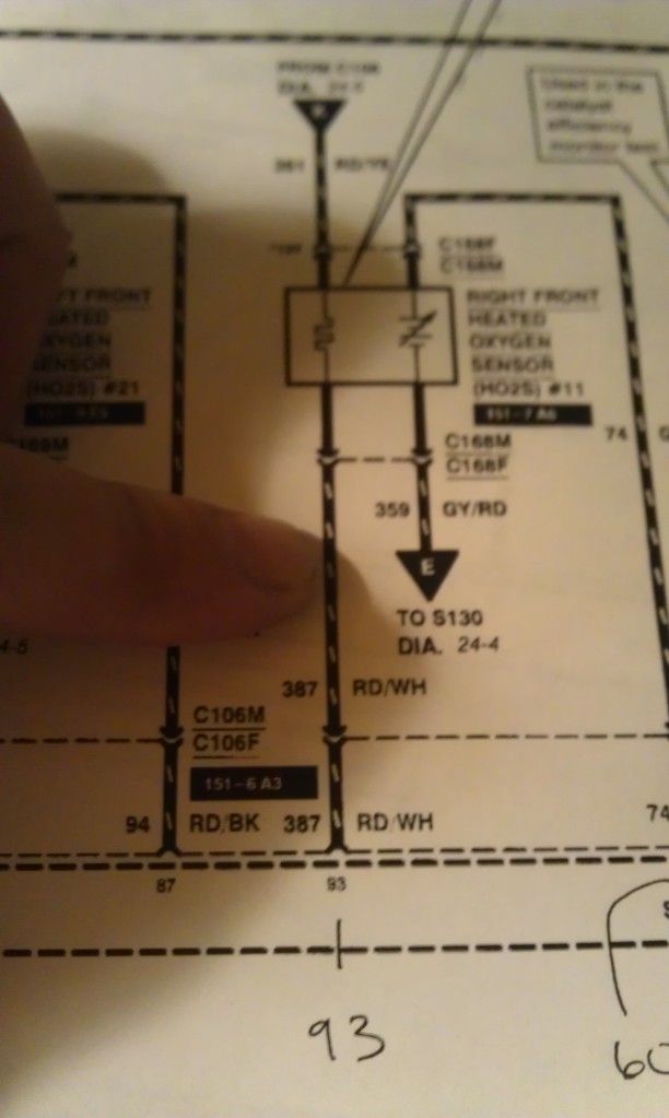
and herewhich i suspect is normal)
has anyone ever seen this or know what could be the problem?! in my mind it sounds like the harness is cut somewhere or something. but i thought id post this fun (lol) puzzle and see if i get lucky and find someone who knows what could be the problem (lol) also do you guys think the sensor is shot now?! i mean its kinda like a direct short isn't it?
and heres where it connects to the pcm and gets a 0v reading and is functioning properly. i believe this is either grounded in the pcm or it sends a reading to the pcm.
OK... on the passenger side i get a 12v reading when i ground my meter both
here
which is the one i suspect shouldnt be 12v)and here
which i suspect is normal)has anyone ever seen this or know what could be the problem?! in my mind it sounds like the harness is cut somewhere or something. but i thought id post this fun (lol) puzzle and see if i get lucky and find someone who knows what could be the problem
 08-17-2012, 03:07 AM
#2
TECH SAVANT
Join Date: Dec 2006
Location: Saint Augustine, FL
Posts: 10,938
Here's an annotated wiring diagram for O� sensor 21, driver's side front:

The RD/YE wire is connected to a +12 V source that is hot in START or RUN, it supplies power to the sensor's heater;
The YE/LB wire is switched to ground by the PCM (it's really a MOSFET transistor, not an actual switch) to activate the heater when the exhaust gas cannot keep it hot enough to work properly. Platinum/Zirconia O� sensors must be hotter than 662�F to work at all, with 950�F or more to work optimally--you can read more about how they work here.
When the PCM is not activating the heater, you will observe +12 V on both the RD/YE and RD/LB wires--this is because the heater's ground connection, the RD/LB wire is left "floating", I.e. not connected to anything.
So when you meter between the RD/YE wire and ground you will read the +12V supply, and when you meter between the YE/LB you will read the +12 V supply through the heater's resistance, which is only 3.3 Ω. Most modern multimeters have 10MΩ or better input impedance making the 3.3 Ω in series with the +12V and the meter irrelevant.
The voltage drop caused by the heater would be only 0.00000396 V, 3.96 μV; so instead of reading +12 V, it would read +11.999996 V.
When the PCM turns on the heater you would still read +12 V between the RD/YE wire and ground, but 0 V between the YE/LB wire and ground as the PCM has closed that "switch".
The GY/RD wire is the sensor's signal "ground", it connects to the "signal return" on the PCM, as dedicated ground circuit for the various sensors. You should always observe 0 V or close to it between this wire and ground.
The RD/BK wire is the O� sensor's output. With the engine warm and idling this should vary between 0.2 and 1.0 V, give or take a bit--like this:

The cycling frequency at idle is less than 1/3rd Hz, which can make reading it with a digital multimeter awkward as the meter's sample rate is probably 1/2 to 1 Hz, and not synchronized with the sensor's output. The only accurate way to measure it is with an oscilloscope.
Here is what it looks like at 2000 rpm, same voltage range but faster cycling at 1 Hz:

Hope this makes sense, and is helpful...
The RD/YE wire is connected to a +12 V source that is hot in START or RUN, it supplies power to the sensor's heater;
The YE/LB wire is switched to ground by the PCM (it's really a MOSFET transistor, not an actual switch) to activate the heater when the exhaust gas cannot keep it hot enough to work properly. Platinum/Zirconia O� sensors must be hotter than 662�F to work at all, with 950�F or more to work optimally--you can read more about how they work here.
When the PCM is not activating the heater, you will observe +12 V on both the RD/YE and RD/LB wires--this is because the heater's ground connection, the RD/LB wire is left "floating", I.e. not connected to anything.
So when you meter between the RD/YE wire and ground you will read the +12V supply, and when you meter between the YE/LB you will read the +12 V supply through the heater's resistance, which is only 3.3 Ω. Most modern multimeters have 10MΩ or better input impedance making the 3.3 Ω in series with the +12V and the meter irrelevant.
The voltage drop caused by the heater would be only 0.00000396 V, 3.96 μV; so instead of reading +12 V, it would read +11.999996 V.
When the PCM turns on the heater you would still read +12 V between the RD/YE wire and ground, but 0 V between the YE/LB wire and ground as the PCM has closed that "switch".
The GY/RD wire is the sensor's signal "ground", it connects to the "signal return" on the PCM, as dedicated ground circuit for the various sensors. You should always observe 0 V or close to it between this wire and ground.
The RD/BK wire is the O� sensor's output. With the engine warm and idling this should vary between 0.2 and 1.0 V, give or take a bit--like this:
The cycling frequency at idle is less than 1/3rd Hz, which can make reading it with a digital multimeter awkward as the meter's sample rate is probably 1/2 to 1 Hz, and not synchronized with the sensor's output. The only accurate way to measure it is with an oscilloscope.
Here is what it looks like at 2000 rpm, same voltage range but faster cycling at 1 Hz:
Hope this makes sense, and is helpful...
 08-23-2012, 03:21 PM
#7
Thread Starter
Join Date: Jul 2012
Location: CA
Posts: 28
Also I do understand how the sensors work.. I realize my first pic is wrong. The heater is a simple +- circuit.. the sensor sends a mv reading. My heater is not working on the passenger side and I have a 12v reading from both the red yellow and the red white wires..
08-23-2012, 03:39 PM
#8
TECH SAVANT
Join Date: Dec 2006
Location: Saint Augustine, FL
Posts: 10,938
The wiring diagram shown above is the driver's side sensor, sensor #21, bank 2 (driver's side), sensor 1 (front)?
I have never tested these voltages without a sensor connected, it could be that the PCM side connection for the heater "ground" is left high (+12V) until the PCM turns the heater on and sinks the current, and that without the proper load it would still read high even after the PCM "closed" the circuit.
As discussed previously a typical multimeter's characteristic input impedance is so high that readings of unloaded open collector or MOSFET "switches" are often misleading.
Connect a sensor and backprobe the connector, or use insulation piercing test probes.

(click image for vendor link)
08-28-2012, 11:31 AM
#9
1st Gear Member
Join Date: Feb 2008
Location: Seattle Washington
Posts: 79
So basically in laymens terms a multimeter won't give u an accurate reading to determine if the sensor is working properly. Diag with a scan tool make this super simple as u can watch the sensor in action making its adjustments. So either buy a crazy expensive diag tool "prolly ford specific" or part someone to fix orrr throw an oreilys o2 at it and if it dosnt work take it back!!!
08-28-2012, 11:51 AM
#10
TECH SAVANT
Join Date: Dec 2006
Location: Saint Augustine, FL
Posts: 10,938
Narrowband O� sensors can be accurately bench tested with a propane torch and a multimeter--here's how.
The sensor heater can be tested by checking the resistance between the two power leads, it should be around 3.3 Ω on our cars, many other/older cars use 6.0 Ω heaters.
The heater power supplied by the PCM can be tested with a multimeter, however you need to have a sensor with a know good heating element and have it connected to the harness.
Right after a cold start you should observe 12 V across the heater connections. After the engine warms the PCM will cycle the heater power to keep the sensor hot, at higher speeds the PCM does not need to power the heater as the exhaust gas will keep it hot...

Thread
Thread Starter
Forum
Replies
Last Post
yourmom6990
Archive - Parts For Sale
2
09-14-2015 10:52 PM
zanemoseley
2005-2014 Mustangs
6
09-06-2015 12:58 PM

