When you click on links to various merchants on this site and make a purchase, this can result in this site earning a commission. Affiliate programs and affiliations include, but are not limited to, the eBay Partner Network.
5.0L (1979-1995) MustangTechnical discussions on 5.0 Liter Mustangs within. This does not include the 5.0 from the 2011 Mustang GT. That information is in the 2005-1011 section.
I'm taking a chance, posting this in the 5.0 section. It's really more of a SN95 concern in general, but it looks like CCRMs are engine-specific, so here goes...
Well, it finally happened. After seeing so many other SN95 owners reporting CCRM failures, I poked around with my meter and narrowed down my recent AC inop issue to the CCRM. (Thanks, Ford, for putting these relays in a "non-serviceable" box...)
I've seen some write-ups on how to avoid buying an entire module by soldering relays on the CCRM. Now I may be a noob at electronics, but soldering a relay like that is totally something that I can handle.
So I removed and opened up my CCRM and took some time to identify the pins and follow the board traces. I found the fuel pump relay, the PCM relay, and the low- and high- speed fan relays. Unfortunately, there's no AC relay in here, like there is in later cars. The AC must be somehow controlled by the other little components on the board (resistors, diodes, etc.), and I'm afraid I'm at a loss on how to proceed here.
I did find a little bit of green corrosion between some solder joints that seemed to maybe be barely bridging them. Those joints are for pins 2(Cooling Fan Motor LOW Output), 3(BATT + Cooling Fan Control Relay's), and 14(Low Fan Control Input). The corrosion was also getting kind of close to the joint for pin 13(Ignition hot in start or run).
I cleaned up the corrosion (but not before taking these pics). I don't see any other visual problems, and I plan to put a fresh layer of conformal coating on the board before re-installation. I also manually tested each of the four relays just for kicks, and sure enough they're still working great.
Could that corrosion have been it? Is there anything else I should do before re-coating the board and putting everything back together? There's no AC relay, but is there a way to bench-test the board's AC clutch circuit first?
I was wondering about that piece. It does appear to be part of the AC circuitry. Is it a relay, though? It has only two terminals, and I see an Ω sign on it:
That's what I was expecting to see. In fact, that's one of the exact pictures I was looking at before I opened mine up. But looking at it again, I see the Ford number on the side starts with "F7" (1997), so that one must be a later revision or something.
My AC was working not too long ago, so the board that I have has to be the correct one, and not some replacement module from a non-AC equipped car. I'm comfortable around relays; they're easy to test. But I don't know how this AC circuit works, since it doesn't appear to have a regular old electromagnetic relay like I'm used to.
Last edited by Urambo Tauro; 07-30-2017 at 08:23 PM.
Oh, and BTW, that white resistor seems to be okay (if I'm reading the markings correctly). It says 62Ω and I'm guessing that "5%" is a tolerance; testing it shows about 60.0Ω of resistance.
Be sure to check all the components. I have a 94 GT and the cooling fan was seized when I bought it. After replacing the fan, I ordered new fan relays and replaced them. I kept the module as a replacement for the new one I got. This spring the connector fractured on the new one and I put the old one in. It worked 'til hot weather when the fan and A/C would fail at the same time after the engine warmed up and was parked. It was failing when hot. I got a used one to replace it
I forgot to update this thread! Thanks for reminding me.
I started checking components one at a time, but I got stuck when it came to the MOSFET. Despite the numbers printed on it, I couldn't find any specs (not even a data sheet) to determine what kind of readings it was supposed to be giving out. And on top of that, I couldn't match up a new one even if it was bad. That was the dealbreaker for me, and I stopped checking other components.
So I gave in and ordered up a remanufactured CCRM. It worked, and it fixed my AC problem, but before completing the installation, I opened it up to have a look inside.
This is a newer design, which probably came out of a Taurus or something, judging by the Ford number printed on the board. The MOSFET is gone, along with a lot of other components, replaced by a more normal coil-type relay.
On the back side of the board, it's kind of ugly. Solder everywhere, but it doesn't appear to be bridging any circuits that shouldn't be bridged. My guess is, this is to reinforce the traces.
There were a few dry spots without conformal coating. Some was rubbed away from the edge of the board, and some appeared to have burned off during the remanufacturer's repairs. Fortunately, I had bought some in anticipation of fixing my original board, so I used it here. It looks a lot better now, and I feel better about putting it in my engine bay, too.
Last edited by Urambo Tauro; 08-25-2017 at 09:39 AM.
Your persistence in this CCRM thing is to be commended! Not to mention your knowledge of electrical principles. A similar thread on another forum produced a large amount of static and friction, with members both denouncing and applauding the decision to employ a "module" to do the simple work of electromagnetic relays.
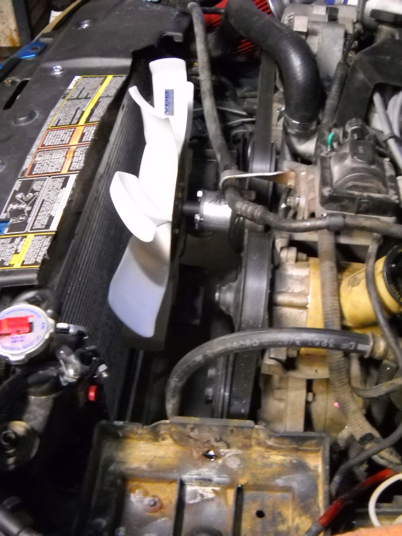
I bought an SN95 in May, a '94 GT, 5.0 HO. Since then, I've gotten rid of the fan entirely, the idiotically-large radiator catch-bottle, the steel bracket supporting both that and the CCRM, which was easily relocated to the RH fender apron. Intent was to get a bigger than 1-core radiator in there; that's still on-hold. With daily temps. of 110` or more, it's cooling perfectly well with a '93-spec Fox fan n& clutch. Left idling with A/C on, gauge reaches half-way through "normal", whereas with the electric fan, it cycled back & forth from highest normal to about 1/4 of the way up. Hated that.
Someone challenged me to design a replace kit to get rid of the CCRM. Entirely possible, but unknowns exist regarding PCM involvement (CEL possibilities). Here's what it looks like now, with all that junk moved away from between radiator & water pump:
 07-30-2017, 03:08 PM