Fuel pump nightmare
 11-14-2012, 01:07 AM
#1
Thread Starter
Join Date: Nov 2012
Location: GA
Posts: 8
Short story of what happened, last year re did wire tuck to a more complicated version, fried 1 ecm found out a ground was hooked to starter relay, forgot what pin it was or were it went to but i can find out if needed, so after that got the ground fixed and the new ecm fixed other issues i had i guess to a burnt ecm. Well drove car maybe 3 times and it sat for about 3 months went to fire it up no fuel pump prime so of course i ground the test port, pump runs and before it would start with it jumpered[last year when had similar issue] but now it wont start, haven't checked for spark but fuel is going through the rail. Ok so i checked everything i could think of and heres the results. this was a 4cyl to 5.0 conversion who ever wired it gives me headaches thinking of it.
PIN-20,40,60 = grounds good
PIN 19 to inertia switch
PIN 22 goes to test port and tan fuel pump wire relay
Inertia switch- Red=12v an Red/Blk=5v this is not good if i remember right
Fuel Pump Relay
Yellow=12v
Pink/Blk=0v
Red/Blk=11.8v
Tan=5.5v
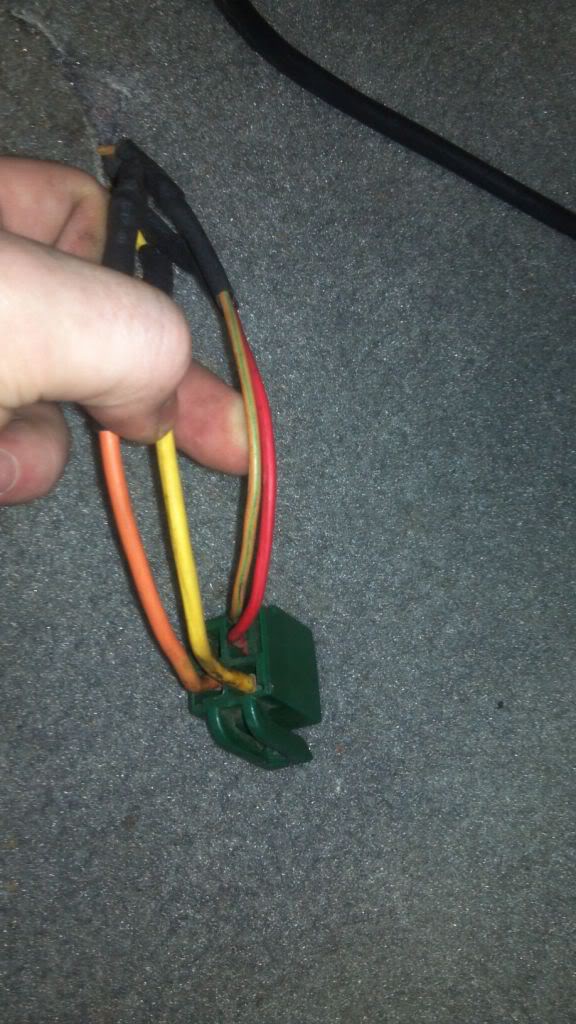
My fuel pump relay is as follow +1 +4
1=yellow
2=red/blk +2
3=tan/green
4=pnk/blk +3
PIN-20,40,60 = grounds good
PIN 19 to inertia switch
PIN 22 goes to test port and tan fuel pump wire relay
Inertia switch- Red=12v an Red/Blk=5v this is not good if i remember right
Fuel Pump Relay
Yellow=12v
Pink/Blk=0v
Red/Blk=11.8v
Tan=5.5v
My fuel pump relay is as follow +1 +4
1=yellow
2=red/blk +2
3=tan/green
4=pnk/blk +3
 11-14-2012, 04:17 PM
#4
6th Gear Member
Join Date: Nov 2006
Location: Spfld, MA
Posts: 9,240
Its a bit weird here, because you have wiring colors that shouldn't exist. What I mean by that is.. in 1990 Ford changed the way the fuel pump wiring was. You seem to have wiring colors for pre-1990 on the inertia switch, but everything else is post-1990.
Light brown/Orange Pin #22 wire, that should also be going to pin 1 on relay.
Pink/Black on the relay (pin #3) should be full time 12v on an 18ga fuseable link up near the starter solenoid.
Dark Green/yellow at Pin #19 should go to a splice-out, to which it goes to pin 4 on the relay, and the other end goes to the input side of the inertia switch.
The output side of your inertia switch should also be 12v.
If I were you I'd take the two wires off the inertia switch and temp-splice them together, see if your results change.
11-14-2012, 10:14 PM
#5
Thread Starter
Join Date: Nov 2012
Location: GA
Posts: 8
Its a bit weird here, because you have wiring colors that shouldn't exist. What I mean by that is.. in 1990 Ford changed the way the fuel pump wiring was. You seem to have wiring colors for pre-1990 on the inertia switch, but everything else is post-1990.
Light brown/Orange Pin #22 wire, that should also be going to pin 1 on relay.
Pink/Black on the relay (pin #3) should be full time 12v on an 18ga fuseable link up near the starter solenoid.
Dark Green/yellow at Pin #19 should go to a splice-out, to which it goes to pin 4 on the relay, and the other end goes to the input side of the inertia switch.
The output side of your inertia switch should also be 12v.
If I were you I'd take the two wires off the inertia switch and temp-splice them together, see if your results change.
Light brown/Orange Pin #22 wire, that should also be going to pin 1 on relay.
Pink/Black on the relay (pin #3) should be full time 12v on an 18ga fuseable link up near the starter solenoid.
Dark Green/yellow at Pin #19 should go to a splice-out, to which it goes to pin 4 on the relay, and the other end goes to the input side of the inertia switch.
The output side of your inertia switch should also be 12v.
If I were you I'd take the two wires off the inertia switch and temp-splice them together, see if your results change.
11-14-2012, 10:23 PM
#6
Thread Starter
Join Date: Nov 2012
Location: GA
Posts: 8
Its a bit weird here, because you have wiring colors that shouldn't exist. What I mean by that is.. in 1990 Ford changed the way the fuel pump wiring was. You seem to have wiring colors for pre-1990 on the inertia switch, but everything else is post-1990.
Light brown/Orange Pin #22 wire, that should also be going to pin 1 on relay.
Pink/Black on the relay (pin #3) should be full time 12v on an 18ga fuseable link up near the starter solenoid.
Dark Green/yellow at Pin #19 should go to a splice-out, to which it goes to pin 4 on the relay, and the other end goes to the input side of the inertia switch.
The output side of your inertia switch should also be 12v.
If I were you I'd take the two wires off the inertia switch and temp-splice them together, see if your results change.
Light brown/Orange Pin #22 wire, that should also be going to pin 1 on relay.
Pink/Black on the relay (pin #3) should be full time 12v on an 18ga fuseable link up near the starter solenoid.
Dark Green/yellow at Pin #19 should go to a splice-out, to which it goes to pin 4 on the relay, and the other end goes to the input side of the inertia switch.
The output side of your inertia switch should also be 12v.
If I were you I'd take the two wires off the inertia switch and temp-splice them together, see if your results change.
Pin #1 on relay the yellow wire has 12v key on and off so is this wrong or?
11-15-2012, 10:57 AM
#7
6th Gear Member
Join Date: Nov 2006
Location: Spfld, MA
Posts: 9,240
Hmmm...... OK admittedly I'm a tad confused here, kinda one of those things where you need to be there. I'll post both diagrams for you, pre-1990 and post-1990.
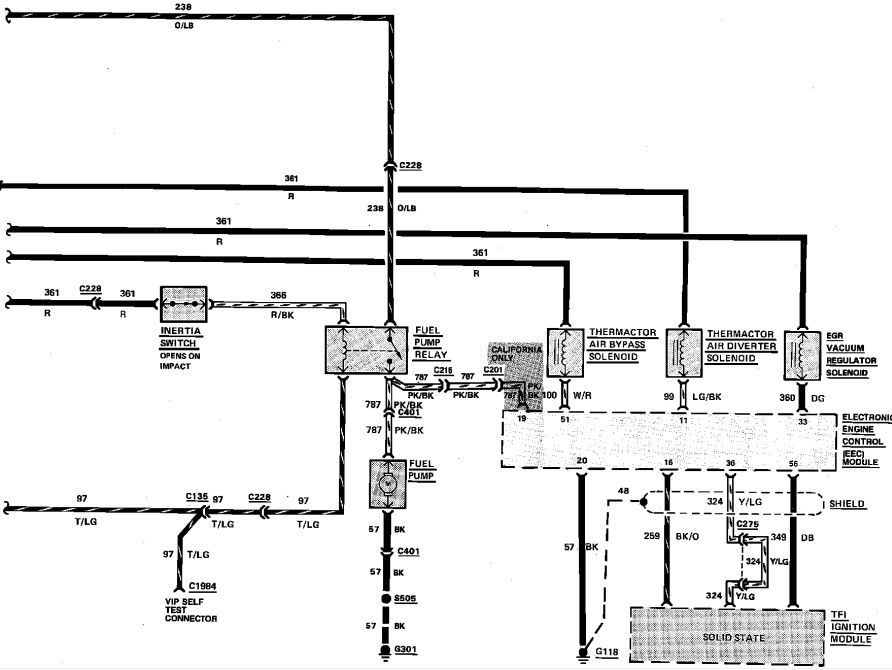
This one is pre-1990.
In this diagram, the red wire on the front side of the inertia switch comes from a large splice that powers all the solenoids visible in the diagram. This large splice originates from PIN 57 of the ECM.
The tan/light green off the relay goes to PIN 22.
The orange/light brown goes off to the starter solenoid with a fuseable link near the end.
__________________________________________________ _
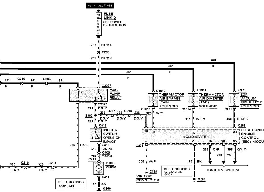
This one is post-1990
The red wire incoming at PIN 2 of the relay is the same big splice as the earlier picture, originating from PIN 57 of the ECM.
Light brown/orange does the same as Tan/Light Green of the previous picture, T's out to self test connector and PIN 22 of the ECM
__________________________________________________ _______
The only real difference between the two is the way that the inertia switch is wired.
Pre-1990 uses the inertia switch as a signal switch for the relay.
Post-1990 uses the inertia switch as a "fuse"(so to speak) inbetween the relay and the pump.
What you wanna do here is copy the diagram that most closely resembles the wiring you have.
This one is pre-1990.
In this diagram, the red wire on the front side of the inertia switch comes from a large splice that powers all the solenoids visible in the diagram. This large splice originates from PIN 57 of the ECM.
The tan/light green off the relay goes to PIN 22.
The orange/light brown goes off to the starter solenoid with a fuseable link near the end.
__________________________________________________ _
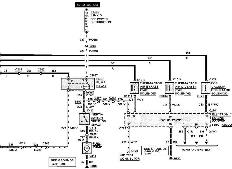
This one is post-1990
The red wire incoming at PIN 2 of the relay is the same big splice as the earlier picture, originating from PIN 57 of the ECM.
Light brown/orange does the same as Tan/Light Green of the previous picture, T's out to self test connector and PIN 22 of the ECM
__________________________________________________ _______
The only real difference between the two is the way that the inertia switch is wired.
Pre-1990 uses the inertia switch as a signal switch for the relay.
Post-1990 uses the inertia switch as a "fuse"(so to speak) inbetween the relay and the pump.
What you wanna do here is copy the diagram that most closely resembles the wiring you have.
Last edited by mattdel; 11-15-2012 at 01:21 PM.
11-16-2012, 11:36 PM
#8
Thread Starter
Join Date: Nov 2012
Location: GA
Posts: 8
Hmmm...... OK admittedly I'm a tad confused here, kinda one of those things where you need to be there. I'll post both diagrams for you, pre-1990 and post-1990.
This one is pre-1990.
In this diagram, the red wire on the front side of the inertia switch comes from a large splice that powers all the solenoids visible in the diagram. This large splice originates from PIN 57 of the ECM.
The tan/light green off the relay goes to PIN 22.
The orange/light brown goes off to the starter solenoid with a fuseable link near the end.

__________________________________________________ _
This one is post-1990
The red wire incoming at PIN 2 of the relay is the same big splice as the earlier picture, originating from PIN 57 of the ECM.
Light brown/orange does the same as Tan/Light Green of the previous picture, T's out to self test connector and PIN 22 of the ECM
__________________________________________________ _______
The only real difference between the two is the way that the inertia switch is wired.
Pre-1990 uses the inertia switch as a signal switch for the relay.
Post-1990 uses the inertia switch as a "fuse"(so to speak) inbetween the relay and the pump.
What you wanna do here is copy the diagram that most closely resembles the wiring you have.
This one is pre-1990.
In this diagram, the red wire on the front side of the inertia switch comes from a large splice that powers all the solenoids visible in the diagram. This large splice originates from PIN 57 of the ECM.
The tan/light green off the relay goes to PIN 22.
The orange/light brown goes off to the starter solenoid with a fuseable link near the end.
__________________________________________________ _
This one is post-1990
The red wire incoming at PIN 2 of the relay is the same big splice as the earlier picture, originating from PIN 57 of the ECM.
Light brown/orange does the same as Tan/Light Green of the previous picture, T's out to self test connector and PIN 22 of the ECM
__________________________________________________ _______
The only real difference between the two is the way that the inertia switch is wired.
Pre-1990 uses the inertia switch as a signal switch for the relay.
Post-1990 uses the inertia switch as a "fuse"(so to speak) inbetween the relay and the pump.
What you wanna do here is copy the diagram that most closely resembles the wiring you have.