When you click on links to various merchants on this site and make a purchase, this can result in this site earning a commission. Affiliate programs and affiliations include, but are not limited to, the eBay Partner Network.
Installing gt40P heads & Cobra Manflow what plugs?
1988 project starts tomorrow on engine improvement gt40P heads and Cobra Manflow. Easy question for you guys. What spark plugs should I install? and any special concerns with the process? My baby brother in coming in to do the work and I'm the gopher for the project.
Installing gt40P heads & Cobra Manflow what plugs?
semoorma, Aluminum heads: Autolite 3924. Iron heads: Autolite copper 764. Autolite 765 is one step hotter than the stock 764s. Gap at .045-.050. These are for non-aspired engines.
I assume you're not required to go through emissions testing,but if you are,know that the gt40p's dont have thermactor ports for the smog system.Im not sure if you've got stock or aftermarket headers?? GT40p's might/might not require new headers due to their spark plug angle,so keep this in mind.If you've got the stock cam in place and you decide to step up to a better one,right now would be the perfect time to do it since the heads are gonna be off.However,if you've still got SD,a maf conversion will be needed,in order to run an aftermarket cam.If you leave the stock cam in place,the heads & intake will work fine with speed density (if you havent converted to maf yet) If you do decide to keep the stock cam,you can always swap to 1.7 rockers to give you some extra lift without the additional cost/labor of a cam change.That'll increase lift from .445" to .475"...........
Im not sure if you're sourcing the heads & intake from a junkyard,online or locally,but regardless,if it hasnt been done yet by the seller,the valvesprings need to be replaced before you install the heads.And yes,this needs to be done even if you're keeping the stock cam, so make sure you verify this with the seller,unless of course you're buying them from a junkyard.I believe Ford Racing,Crane & TFS have the spring kit for
this upgrade,which includes springs,
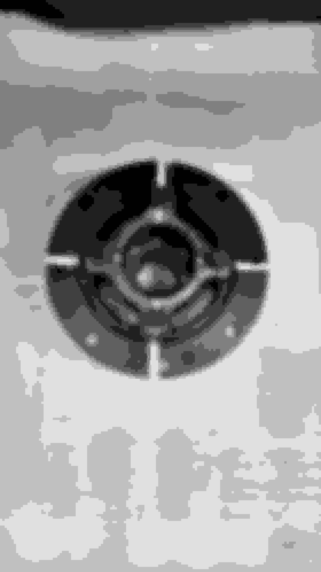
keepers,retainers and possibly valvestem seals too?? Once you get the heads installed and you're ready to tighten the rockers down,the easiest way to do it is by drawing lines/dots (using Witeout) on the harmonic balancer to represent crank rotation,in degrees.
** To make lines on the balancer **
1) Get the #1 piston to tdc on the compression stroke (in order for #1 to be at tdc,you should feel air coming from the plug hole and the 0� mark on the balancer should be aligned with the timing pointer )
2) Draw a line/dot on the front of the balancer at the 0� mark
3) Draw 3 more lines on the balancer,equal distances apart,using a ruler or tape measure.
4) Each line will now represent 90� of crank rotation,so you don't have to guess.
Line=
1= 0�
2= 90�
3= 180�
4= 270�
*Once these lines are put on the balancer*
1) Get the number 1 piston at tdc on the compression stroke
2) Lash/tighten the two rocker bolts for the number 1 cylinder
3) Rotate the crankshaft CW to the next line you made (which represents 90� of crank rotation)
4) Tighten the rockers for the number 3 cylinder.
5) Continue this process,following the firing order, until the remaining cylinders are done.
The picture below shows a sloppy example of how the lines will appear.
Last edited by wbrockstar; 05-07-2018 at 11:15 AM.
Thanks for the heads up. My brother and I started today and have progress to getting ready to pull the stock manifold assembly. Any tricks suggestion on doing this? Right now we're trying to separate the mass air flow thing from the main body. Seems almost welded on. Looks like we have to disassemble a lot of stuff from the manifold. Gonna be interesting. All suggestion will be read with great interest.
Yeah the throttle body & egr spacer are notorious for welding to the intake. They actually weld more to the 4 long studs that hold them to the intake.Unfortunately I don't have any tricks for removing them easily other than to pry a little then as you expose more of the studs (between the spacer & intake) ,clean the threads with a dremel/drill & a wire brush then push the tbody /spacer back towards the intake then away from the intake ,so the back & forth movement will hopefully help the parts break free from the corrosion on the studs.Its just time consuming.
As far as the wiring harnesses go,the easiest way to help you remember which harness plugs into which sensor is,
wrap white tape around the sensor plug and tape around the harness plug that mates to the sensor, write the same number or letter on both plugs then you can disconnect them.Reconnection is quick and easy,just connect letter D plug into letter D sensor.
Dont re-use the lower intake bolts. Use ARP's or another quality brand. Ive seen many bolts break off in the head because they were old/cheap. If you get four cheap bolts (the same thread as the intake bolts) & cut the heads off then screw them into the heads so that youll have one bolt positioned at each corner of the lower intake,it'll make installation easy & prevent the gasket from moving while lowering the intake into place.Use the Right Stuff rtv on the intake end rails instead of using cork/rubber gaskets.Make sure youve got all the wiring pulled back & out of the way,so a wire doesn't get pinched between the intake & block/heads.Make sure you reconnect the Orange wire (with ring terminal) thats part of the fuel injector harness, to a good ground.Its the ground for the o2 sensors and alot of members fail to reconnect it.The same goes for the secondary ground.Its the flat,braided strap that runs from the driver cylinder head (rear) to the firewall.
Almost everything on the stock upper/lower intake will have to be moved to the gt40 intake. Any vacuum hoses that connect to the underside of the upper intake, should have a hose clamp or ziptie attached ,to prevent the hose from being pulled loose or off.
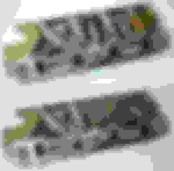
The gt40 intake came with two different sized baffles.A small one & large one.Make sure yours has the larger one.Oil will get drawn in through the pcv valve and puddle in the intake, if youve got the small one.The pictures below show the difference.
Thanks for the comprehensive message. Now to digest it. Think I may have bit off more than I can chew. I.E., took 3 weeks to get the Summit exhaust shorty bolted up as my old hands and arms ain't what they used to be. It is proving to be an interesting experience.
 05-04-2018, 11:31 AM


 Think I may have bit off more than I can chew. I.E., took 3 weeks to get the Summit exhaust shorty bolted up as my old hands and arms ain't what they used to be. It is proving to be an interesting experience.
