When you click on links to various merchants on this site and make a purchase, this can result in this site earning a commission. Affiliate programs and affiliations include, but are not limited to, the eBay Partner Network.
I recently determined I have no power to my am/fm radio (rarely turn it on as I have better things to listen to). After tearing into it found some shoddy electrical bs. 😩. Can you say custom auto sound hack job....
Suffice to say I am planning a remote amp with bluetooth iphone controls and want to do it right.
My question is, based on the electrical schematic for the 1967 coupe which colored wire(s) will provide 12v accessory and 12V constant power. I need to trace back to the ignition and find the original factory wiring (if it still there.... 😬
Looks like 137 is ignition switched power, test it with a volt meter or a light.
See if there is power there with the ignition on, and not when off, but 137
looks like it.
If your radio has no memory feature, like no clock, and no digital station
presets, then it's just one ignition power lead. If you do have a radio with
a memory requirement, get that right from the battery.
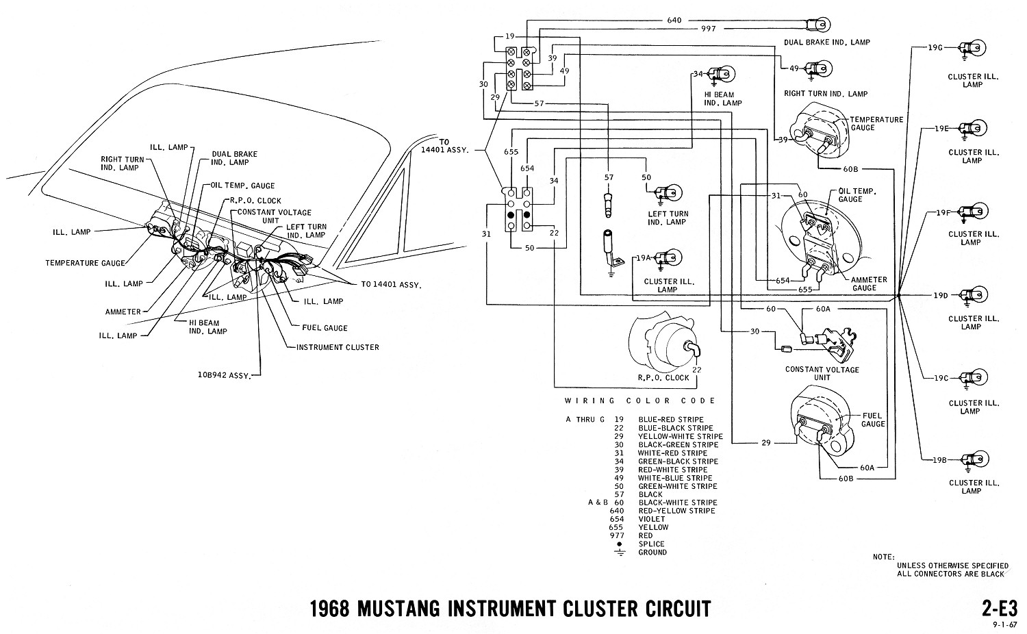
According to that diagram, 19 is the light/dimmer for the radio and dash cluster lights.
It comes right from the light switch. 297 is from the regulator, key on battery (B+).
137 is supposed to power the radio. The 1966 has the same setup, just different
numbers (140 and 19), but the wire configuration is the same.
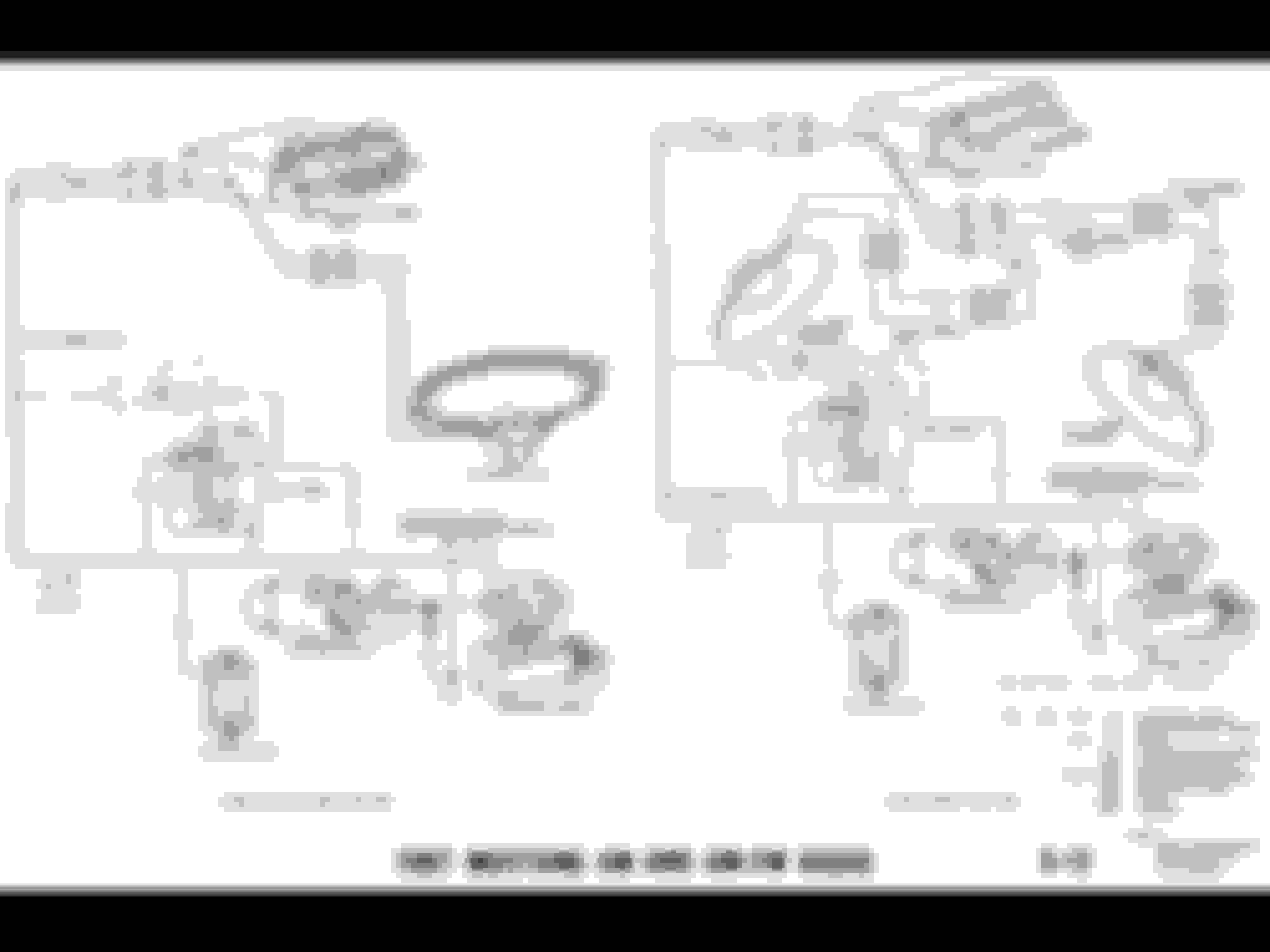
Here is an ignition diagram...
Here you see 25, a splice in from 37a with 37 and 21. Notice 25 in the radio diagram, goes to the light switch.
Here is the cluster diagram:
This diagram shows all the 19s, you see they are lighting, you can't use 19 to power the radio.
67/68 will be the same.
Ok. Thanks for the schematics. I need to dig more. The original wiring is missing so I will find the original wire off the iginition, trace it out and see where it terminates and try to pick it up there.
I also went to CJPP and ordered the electrical manual.
After pulling the instrument cluster and digging around the ignition module, no shi*. I found the original AM radio harness. I double checked swithed power in both accessory and on and it�s good.
Question, Would this also be a good spot to connect a future 12v source for an efi kit?
When you buy an EFI kit, THAT should at least have instructions. There has to be
connections in the engine bay for that. Your coil isn't on all the time, so that should
be switched. Most EFI kits will replace what you have and use existing
wiring, but you may need to add something, but would be out in the engine bay.
Understood. I was looking at a Holley Schematic and it needs 12v direct from the battery as well as 12v ignition switched. I also see a purple wire for cranking positive and dark green for cranking negative.
 06-04-2018, 10:41 PM