Need some help wiring in a boost sensor

 02-28-2009, 05:01 PM
#12
4th Gear Member
Thread Starter
Join Date: Apr 2007
Location: Big Sky Country
Posts: 1,079
Ok so I had it hooked up with the car running, and per the PLX support dude's instructions, used a multimeter (which I had never used before) to measure the unit's output voltage.
Put the negative prong of the multimeter on the bottom left output ground terminal and the positive prong on the bottom right output signal terminal like he said i should.
With the multimeter set on 10 mA, it read almost exactly 100 along the "DC V.mA" line.
So this has to mean the unit is outputting a signal right? So it must not be making it to the livewire. or the livewire firewire input has a faulty connection. Also, the firewire cable is pretty long... is it possible the output voltage isn't strong enough to go the distance of the cable? Erg this is frustrating...
02-28-2009, 05:10 PM
#13

Join Date: Nov 2008
Location: IL
Posts: 17
according to the plx instructions the voltage should be like the following
Vacuum Range (0V = 30.5inHg = -15PSI, 1.66V = 0PSI)
Boost Range (1.66V = 0PSI, 5.0V = 30PSI)
If you disconnect the vacuum hose from the plx device and supply power, you should be reading 0 psi and a voltage of 1.66 volts. 100 millivolts seems very low. If the senor is connected to the car while it is running you should be somewhere around 20inHg vacuum which would be around 1 volt.
02-28-2009, 05:18 PM
#15
Join Date: Nov 2008
Location: IL
Posts: 17
one more thing, what setting did you have the multimeter on when measuring? I just noticed you have V.mA which would measure current. You want to read volts dc.
You should have the multimeter set to vdc or volts dc. If the multimeter has probes the black wire should touch the lower left pin(gnd) under output on the plx device and the red wire should touch the right pin (analog out).
If you have the sensor wired to get power on key on, it should be reading 0 psi when the car is not running with the key on. This should show ~1.66 volts.
02-28-2009, 05:25 PM
#16
4th Gear Member
Thread Starter
Join Date: Apr 2007
Location: Big Sky Country
Posts: 1,079
one more thing, what setting did you have the multimeter on when measuring? I just noticed you have V.mA which would measure current. You want to read volts dc.
It was on DC, just on the 10 mA setting. So i need to have it measuring Volts? what's the difference? Isn't it just a difference of units, like measuring water by mL or by cups? sorry, newb here when it comes to this stuff lol
You should have the multimeter set to vdc or volts dc. If the multimeter has probes the black wire should touch the lower left pin(gnd) under output on the plx device and the red wire should touch the right pin (analog out).
That's what i did, except on the 10 mA setting.
If you have the sensor wired to get power on key on, it should be reading 0 psi when the car is not running with the key on. This should show ~1.66 volts.
02-28-2009, 05:38 PM
#18
Join Date: Nov 2008
Location: IL
Posts: 17
if the multimeter is giving a reading in mA or A, then it is measuring current flowing in amps and not the voltage. This would be the number or milliamps or amps flowing through.
You want the multimeter to be displaying a value in mV or V. This would be in millivolts or volts.
It is hard to say what settings the multimeter should be set on because they are all so different. It sounds like you have the probes connected correctly. It also sounds like you have it set to deal to dc. Now you just need to find out how to set it to read voltage instead of amperage. Some multimeters will have a dial that can be set to different reading types, other may have a mode button that switches between reading types. If you can give the brand and model number, or a picture of the mutimeter, I can try to get you on the right path.
02-28-2009, 05:57 PM
#19
4th Gear Member
Thread Starter
Join Date: Apr 2007
Location: Big Sky Country
Posts: 1,079
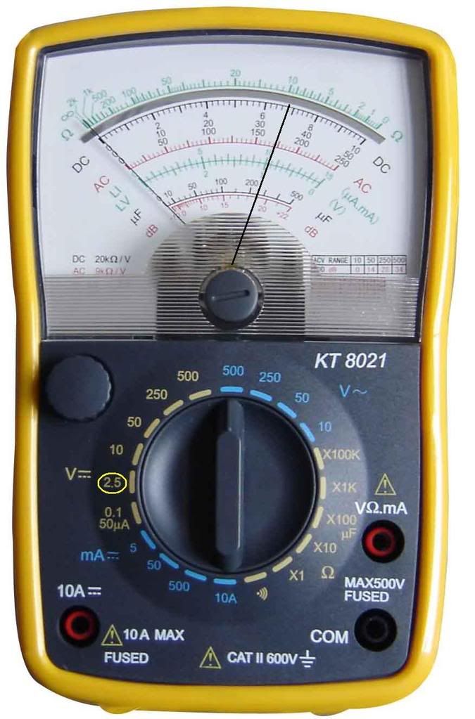
It's just an analog multimeter with a needle, not a digital display. It's this brand, but a little different model. Same idea though

so while set on the 2.5 setting for DC, 170 along the "DC V.mA" line would read about 34 along the ACV line, and about 2.3 on the ohms line. now ohms is resistance, so that can't be right. and ACV must be AC voltage, so that can't be right. So I figured "DC V.mA" would be the line I'm supposed to be reading.
so while set on the 2.5 setting for DC, 170 along the "DC V.mA" line would read about 34 along the ACV line, and about 2.3 on the ohms line. now ohms is resistance, so that can't be right. and ACV must be AC voltage, so that can't be right. So I figured "DC V.mA" would be the line I'm supposed to be reading.