When you click on links to various merchants on this site and make a purchase, this can result in this site earning a commission. Affiliate programs and affiliations include, but are not limited to, the eBay Partner Network.
Hi, I have a 2016 Ford Mustang Ecoboost 2.3l and I need a schematics of the ignition wiring, I am look for the wire that connects from the ignition to all 4 coils, 12v wire can anyone help me?
Basically, you can use any +12 ignition switched source, unless each one
is triggered independently. I see they only have two wires, so I guess
that the ground is where they bolt to the head, one wire is signal, the other
is +12.
Basically, you can use any +12 ignition switched source, unless each one
is triggered independently. I see they only have two wires, so I guess
that the ground is where they bolt to the head, one wire is signal, the other
is +12.
The thing is I need the wire leading to all four coils from the ignition switch because I am trying to install a flamethrower kit and I need to find that wire because I have to connect it to a module.
Oh, I see how this works, they want you to CUT power to the coils, so the unburned fuel
is ignited by the kit... The switch on the kit interrupts power to the coils.. You know this will
throw four misfire codes...
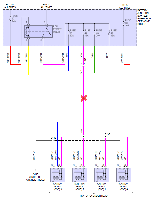
But here is the +12 for the coils:
Highlighted in yellow.
"X" Marks your splice point:
IT may not work if your car still has its Catalytic converters...
It's bad for the pistons and rings, the fuel washes the oil off the cylinder walls,
and rings. You will need to change the oil more often, as it will be saturated with
fuel depending how often you use it.
Last edited by 08'MustangDude; 03-26-2019 at 05:57 PM.
Each coil has the same wire which is purple This is the wire I want to cut in half and then reconnect to two different wires.
Originally Posted by 08'MustangDude
IT may not work if your car still has its Catalytic converters...
It's bad for the pistons and rings, the fuel washes the oil off the cylinder walls,
and rings. You will need to change the oil more often, as it will be saturated with
fuel depending how often you use it.
So I think I found that wire, it leads from the fuse box to the coils, I�m sending pics at the bottom of what I think they are, I�m gonna cut that purple wire in half and then connect each side to the to the provided relay. Im just wondering if that�s the correct before I cut it. And thank you for the heads up
Schematic says it's a violet wire... As long as they all match, from the fuse relay center to the
coil packs.
You can test for continuity. Set the volt meter to measure resistance, touch the red and black leads
together to verify continuity reading.
Pull the fuse for the coil packs, and put the black lead of a volt meter into the leg that feeds the
power to the coils, not the supply side. Then, at the harness, use the red lead of the probe on
the position the wire is, and check for continuity, then you know you got the right wire/color.
Thank you so much!!! It worked, couldn�t do it without you!!.
What wire was it and do you have a picture of the wire. Dm IG: Car_Culture2.3L
[QUOTE=Paul_s550;8649207]
Each coil has the same wire which is purple This is the wire I want to cut in half and then reconnect to two different wires.
So I think I found that wire, it leads from the fuse box to the coils, I�m sending pics at the bottom of what I think they are, I�m gonna cut that purple wire in half and then connect each side to the to the provided relay. Im just wondering if that�s the correct before I cut it. And thank you for the heads

 03-26-2019, 03:33 PM