rebuilding T5 (3&4) slider question
 12-30-2008, 10:07 PM
#1
Moderator
Thread Starter
Join Date: Dec 2005
Location: Hills of California
Posts: 5,208
Hey
I asked this question in my other t5 thread about what pullers to used but I Think its important enough to ask in its own tread.
Im rebuilding my T5...I stared with the out put shaft.
I got the all stuff I wanted to replace on the output shaft replaced and back together. (1st and 2nd gear all blockers, 1&2 slider, all bearings)
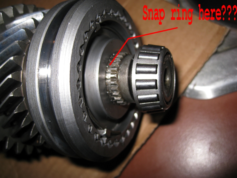
My only question right now is the 3&4 sync assembly (the shift fork engages this assy and it does not have the gear on it) When I pressed it back on the output shaft there was a notch in the spines on the output shaft like a snap ring would go there...The manual never said anything about a snap ring (and none of the snap rings I have fit...at least not perfect) . I pressed the 3&4 slider down so this groove was just clear of the hub (so if a snap ring did go there it could have fit) This notch is at the far end of the output shaft behind the bearing which makes the junction to input shaft.
2) this is the correct depth to press the 3&4 slider right?
1) Is no snap ring here? If there is what type is it (the one without the holes for a snap ring puller or the common type with the holes for the puller)...Pictures anyone?
Thanks
-Gun
I asked this question in my other t5 thread about what pullers to used but I Think its important enough to ask in its own tread.
Im rebuilding my T5...I stared with the out put shaft.
I got the all stuff I wanted to replace on the output shaft replaced and back together. (1st and 2nd gear all blockers, 1&2 slider, all bearings)
My only question right now is the 3&4 sync assembly (the shift fork engages this assy and it does not have the gear on it) When I pressed it back on the output shaft there was a notch in the spines on the output shaft like a snap ring would go there...The manual never said anything about a snap ring (and none of the snap rings I have fit...at least not perfect) . I pressed the 3&4 slider down so this groove was just clear of the hub (so if a snap ring did go there it could have fit) This notch is at the far end of the output shaft behind the bearing which makes the junction to input shaft.
2) this is the correct depth to press the 3&4 slider right?
1) Is no snap ring here? If there is what type is it (the one without the holes for a snap ring puller or the common type with the holes for the puller)...Pictures anyone?
Thanks
-Gun
Last edited by Gun Jam; 12-30-2008 at 10:49 PM.

 12-31-2008, 12:12 AM
#4
Moderator
Thread Starter
Join Date: Dec 2005
Location: Hills of California
Posts: 5,208
Okay Okay
when you pull the slider full engage to 3rd how much space between slider and gear?
mine barely touches and it always has it has marks on the slider where the gear touches it.
on second though that might not really be an accurate measurement..
UGh..now i see a wear mark on the slider like it would have if a snap ring were there..cant see it in that photo tho
Last edited by Gun Jam; 12-31-2008 at 12:15 AM.
12-31-2008, 12:27 AM
#5
in limbo
Join Date: Jan 2007
Location: Iowa
Posts: 7,300
the main shaft is Z spec too? with mine there is no groove cut in the teeth like that. just the splines. and IIRC when the gear is engaged on the gear there isnt any space. you shouldnt see between the hub and blocker ring if thats what you are refering too. the slider overlapse them. the slider shouldnt come off the hub all the way. the shift assembly wont allow you to overshift it that far because of the internal stops.
once you measure the tailshaft with the dial indicator you'll know if you did it right.
yea dont forget to put the detent spring in there
once you measure the tailshaft with the dial indicator you'll know if you did it right.
yea dont forget to put the detent spring in there
12-31-2008, 01:12 AM
#7
in limbo
Join Date: Jan 2007
Location: Iowa
Posts: 7,300
stand the trans up and support it so you have access to input shaft. Set up the dial indicator to read output shaft endplay and zero it out, after pulling down on the input shaft. With a block of wood, force the input shaft up, and read the endplay on the dial indicator; pull down on and rotate the input shaft, and repeat the reading. do this like three to four times to make sure you get consistent reading. now you can put the trans back down and remove input shaft bearing retainer, being careful not to move the input shaft itself. remove the bearing race from inside the retainer, and install shim of the same thickness as the observed endplay. this will make it .000” endplay i think faactory allowance is like .002". reinstall the bearing race
 12-31-2008, 11:48 AM
#10
in limbo
Join Date: Jan 2007
Location: Iowa
Posts: 7,300
no, push it on as far as it will go. put it back in the tranny. install the input shaft and bearing retainer and proceed with checking output shaft endplay. if everything checks out, seal that beast up and get her back in the car 