

 Oct 26, 2015, 02:17 PM
Last edit by: IB Advertising
See related guides and technical advice from our community experts:
Browse all: Lighting Guides
- Ford Mustang Gt 1996 to 2004: How to Slow Down Sequential Tail Light Rate
Step by step instructions for do-it-yourself repairs
Browse all: Lighting Guides

How To: Slow Down Sequential Tail Light Rate
Thread Starter
2nd Gear Member
Joined: Aug 2010
Posts: 160
From: PA
I installed the WebElectric Products sequential tail light kit for my 2004 GT and am very pleased with the product. I got the STS-1M, splice-in kit because I have experience with electronics. No soldering is required with this kit - comes with quick-splice and wire nuts. Their instructions are very straight forward with pictures, so I'm not going to explain how to install the kit here. Visit their website for install instructions...
http://www.webelectricproducts.com/
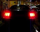
Once I installed the kit, the blinks seemed too fast and I read similar complains on the forum with no real solution. Three blinks now need to flash in the time one happened before. Here is a video of my lights before...
This does not have to do with the kit, but the actual turn signal flasher module under the dash. The stock rate is about 80 flashes per minute. I did find a modified flasher module online for $25 you can buy to slow down the rate, but my fix is for $1.19. Maybe I should modify and sell them.
*This mod requires basic knowledge of electronics and how to solder!
1) First find the turn signal flasher module. It is located under the driver's side dash above/to the right of the gas pedal. It is clipped on the medal structure of the center console. Turn on your signals and listen for it. Mine was yellow...

2) Pull it down and unplug it from the wire harness. Now you will need to get the electronics out of the case. I just used a couple small straight screwdrivers and needle nose pliers to gentle pull it out.
3) The stock flasher has a 3.3 uf capacitor. This is what determines the flash rate. The more capacitance, the slower the rate - so we need to add another capacitor.
4) All you have to do is install a 1uf electrolytic capacitor across the 3.3uf cap that's already there. That will slow it down nicely. I found a 1uf capacitor at Radio Shack for $1.19. Just take the new capacitor and place it on top the existing one. Make sure the direction of the writing matches. With it installed like this it will fit perfectly into the case.
-You could also take the 3.3uf cap out and install a higher capacitance capacitor in its place but this would require soldering directly onto the computer chip board. Not sure what number you would need either. 4.3uf?
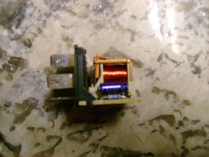
5) Cut the leads to the proper length so you can wrap the 1 cap leads carefully around the leads of the 3.3 cap a time or two with a small pair of pliers. Make sure the leads are not touching any wires or metal! After you are happy with how it is mounted, just solder the leads together. Should look like this...

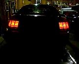
6) Push the module back into the yellow case, plug it back in, slide it onto the mount under the dash and enjoy your new flash rate. I think it makes the modification way more noticeable. It now flashes about 62 times per minute...
*This will also slow down the front turn signal rate and the rate at which the first sequence of the brake light application comes on. I tested it and still seems safe - use your own judgment on this.
I would like to thank Lawrence from WebElectric Products for the quality kit and for answering my questions about this modification. He responded to my emails very fast and told me which capacitor I would need. Thanks again!
http://www.webelectricproducts.com/
Once I installed the kit, the blinks seemed too fast and I read similar complains on the forum with no real solution. Three blinks now need to flash in the time one happened before. Here is a video of my lights before...
This does not have to do with the kit, but the actual turn signal flasher module under the dash. The stock rate is about 80 flashes per minute. I did find a modified flasher module online for $25 you can buy to slow down the rate, but my fix is for $1.19. Maybe I should modify and sell them.
*This mod requires basic knowledge of electronics and how to solder!
1) First find the turn signal flasher module. It is located under the driver's side dash above/to the right of the gas pedal. It is clipped on the medal structure of the center console. Turn on your signals and listen for it. Mine was yellow...
2) Pull it down and unplug it from the wire harness. Now you will need to get the electronics out of the case. I just used a couple small straight screwdrivers and needle nose pliers to gentle pull it out.
3) The stock flasher has a 3.3 uf capacitor. This is what determines the flash rate. The more capacitance, the slower the rate - so we need to add another capacitor.
4) All you have to do is install a 1uf electrolytic capacitor across the 3.3uf cap that's already there. That will slow it down nicely. I found a 1uf capacitor at Radio Shack for $1.19. Just take the new capacitor and place it on top the existing one. Make sure the direction of the writing matches. With it installed like this it will fit perfectly into the case.
-You could also take the 3.3uf cap out and install a higher capacitance capacitor in its place but this would require soldering directly onto the computer chip board. Not sure what number you would need either. 4.3uf?
5) Cut the leads to the proper length so you can wrap the 1 cap leads carefully around the leads of the 3.3 cap a time or two with a small pair of pliers. Make sure the leads are not touching any wires or metal! After you are happy with how it is mounted, just solder the leads together. Should look like this...
6) Push the module back into the yellow case, plug it back in, slide it onto the mount under the dash and enjoy your new flash rate. I think it makes the modification way more noticeable. It now flashes about 62 times per minute...
*This will also slow down the front turn signal rate and the rate at which the first sequence of the brake light application comes on. I tested it and still seems safe - use your own judgment on this.
I would like to thank Lawrence from WebElectric Products for the quality kit and for answering my questions about this modification. He responded to my emails very fast and told me which capacitor I would need. Thanks again!
Last edited by Martinarcher64; Apr 13, 2011 at 03:33 PM.
Underboss
Joined: Jan 2006
Posts: 20,272
From: Helaware
Well written my friend
Added to the HOW TO section https://mustangforums.com/forum/4-6l...ted-often.html
scroll to bottom
Added to the HOW TO section https://mustangforums.com/forum/4-6l...ted-often.html
scroll to bottom
TECH SAVANT
Joined: Dec 2006
Posts: 10,937
From: Saint Augustine, FL
Good write-up!
The nearest standard value for a single capacitor would be 4.7μF, this would get the blink rate down to 56/minute or so.
One comment--the fundamental property of capacitors is capacitance, not resistance...
The nearest standard value for a single capacitor would be 4.7μF, this would get the blink rate down to 56/minute or so.
One comment--the fundamental property of capacitors is capacitance, not resistance...
Last edited by cliffyk; Apr 13, 2011 at 02:32 PM.
TECH SAVANT
Joined: Dec 2006
Posts: 10,937
From: Saint Augustine, FL
3rd Gear Member
Joined: Apr 2010
Posts: 530
From: Raleigh, NC

Thread Starter
2nd Gear Member
Joined: Aug 2010
Posts: 160
From: PA
TECH SAVANT
Joined: Dec 2006
Posts: 10,937
From: Saint Augustine, FL
Cool... The write-up was done so well, why not make it perfect...
