


Sticky Request: ECT Testing


Thread Starter
6th Gear Member
Joined: Nov 2006
Posts: 9,239
From: Spfld, MA
 Sticky Request: ECT Testing
Ok, so I've seen a bunch of people asking about running rich, what causes it, etc... Because of the age of our fox body's, the engine coolant temp(ECT) sensor is more than likely the cause, if everything else seems normal. But no one knows the proper way to test it. Well, here ya go. Pics provided.
Alot of people think that the computer uses the same sensor as the gauge. This is false. The sender for the temp gauge in your dash is located just to the right of the distributor.
The sensor that the computer uses is on the other side, near the #1 cylinder injector.
The Engine Coolant Temperature (ECT) sensor is threaded into a coolant passage with the sensing bulb extending into the coolant.
The ECT sensor is a negative temperature coefficient sensor, meaning that as the temperature of the sensor increases, the resistance will decrease. As the resistance value changes, the signal sensed by the Electronic Control Assembly (ECA) also changes. The ECA reads the varying sensor resistance and determines the engine operating temperature, using this information to optimize the air/fuel mixture and ignition timing.
The ECT sensor will also set a fault code when the ECA determines the output signal to be out of the normal operating range.
^^^ not always true, if the values are still within range but still subsequently wrong, no code will be set.
The ECT sensor has 2 wires in it's harness connector; a black with white stripe, thats the ground.
The other wire is Light Gray with a Yellow stripe, this is the one we will be testing.
Most Multimeters are capable of testing many different ranges of resistance, we only need one that can measure up to around 75 ohms. Select Ohms(anything above 75 is ok). Look for this symbol. Ω
The engine doesn't need to be running, only the key on, but you should test at different temps, and see the differences.
With engine at desired temp, place the negative lead of the meter into the ground wire of the connecter, being sure that it is touching the metal inside the connector.
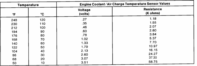
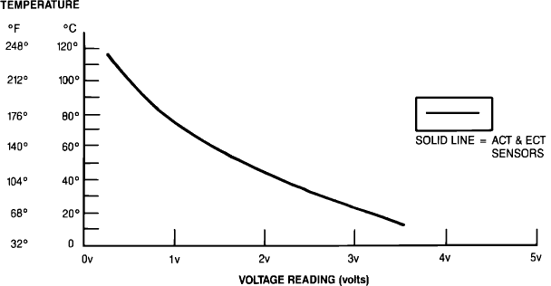
Place the positive lead of the meter into the connector Gray wire, and use charts below
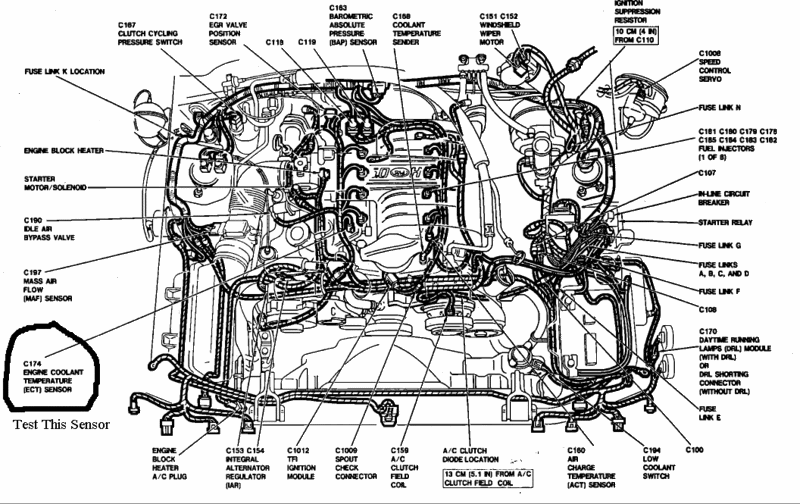
Alot of people think that the computer uses the same sensor as the gauge. This is false. The sender for the temp gauge in your dash is located just to the right of the distributor.
The sensor that the computer uses is on the other side, near the #1 cylinder injector.
The Engine Coolant Temperature (ECT) sensor is threaded into a coolant passage with the sensing bulb extending into the coolant.
The ECT sensor is a negative temperature coefficient sensor, meaning that as the temperature of the sensor increases, the resistance will decrease. As the resistance value changes, the signal sensed by the Electronic Control Assembly (ECA) also changes. The ECA reads the varying sensor resistance and determines the engine operating temperature, using this information to optimize the air/fuel mixture and ignition timing.
The ECT sensor will also set a fault code when the ECA determines the output signal to be out of the normal operating range.
^^^ not always true, if the values are still within range but still subsequently wrong, no code will be set.
The ECT sensor has 2 wires in it's harness connector; a black with white stripe, thats the ground.
The other wire is Light Gray with a Yellow stripe, this is the one we will be testing.
Most Multimeters are capable of testing many different ranges of resistance, we only need one that can measure up to around 75 ohms. Select Ohms(anything above 75 is ok). Look for this symbol. Ω
The engine doesn't need to be running, only the key on, but you should test at different temps, and see the differences.
With engine at desired temp, place the negative lead of the meter into the ground wire of the connecter, being sure that it is touching the metal inside the connector.
Place the positive lead of the meter into the connector Gray wire, and use charts below

Thread Starter
6th Gear Member
Joined: Nov 2006
Posts: 9,239
From: Spfld, MA
RE: Sticky Request: ECT Testing
yah i do
EGR OPENING VOLTAGES
BLACK SENSOR GRAY SENSOR
0% .90 volts .35 volts
10% 1.25 volts .75 volts
20% 1.65 volts 1.10 volts
30% 1.95 volts 1.45 volts
40% 2.30 volts 1.80 volts
50% 2.65 volts 2.15 volts
60% 3.00 volts 2.50 volts
70% 3.35 volts 2.85 volts
80% 3.70 volts 3.20 volts
90% 4.05 volts 3.55 volts
100% 4.40 volts 3.90 volts
EGR OPENING VOLTAGES
BLACK SENSOR GRAY SENSOR
0% .90 volts .35 volts
10% 1.25 volts .75 volts
20% 1.65 volts 1.10 volts
30% 1.95 volts 1.45 volts
40% 2.30 volts 1.80 volts
50% 2.65 volts 2.15 volts
60% 3.00 volts 2.50 volts
70% 3.35 volts 2.85 volts
80% 3.70 volts 3.20 volts
90% 4.05 volts 3.55 volts
100% 4.40 volts 3.90 volts

6th Gear Member
Joined: Feb 2006
Posts: 5,956
From: Howard City, MI
RE: Sticky Request: ECT Testing
Well, if I were to pull a code for low voltage, that would mean it is only at certain times? I mean, I was thinking that there was a normal open and a normal closed range on it. I just see people running simulators that are constant, just I was just curious. Thanks for the help
Thread Starter
6th Gear Member
Joined: Nov 2006
Posts: 9,239
From: Spfld, MA
RE: Sticky Request: ECT Testing
A low voltage on the EGR could be caused by carbon buildup, or weak vacuum. The PCM knows how much voltage should be there during throttle and what not. If the voltage doesn't match the pre-programmed parameters, you will get the code. If it goes away, sounds like vacuum to me.

5th Gear Member
Joined: Jan 2006
Posts: 3,926
From: Puerto Rico
RE: Sticky Request: ECT Testing
ORIGINAL: 5.0stanger
what is it normal operating range?
what is it normal operating range?
EGR Closed Maximum = .67vdc or code 35 is logged
EGR Open Maximum = 4.81vdc or code 34 is logged
