Charlene
 01-05-2009, 06:34 PM
#11
3rd Gear Member
Thread Starter
Join Date: Jul 2005
Location: El Paso, TX
Posts: 630
I was planning on keeping the EFI as well but with the motor I plan on building the fuel system to feed it via EFI would just cost way too much.

 01-24-2009, 08:12 PM
#13
3rd Gear Member
Thread Starter
Join Date: Jul 2005
Location: El Paso, TX
Posts: 630
updated the website a bit today if anyone wants to check it out and maybe leave some comments.
https://mspace.utep.edu/amacias2/Cha...ome%20Page.htm
https://mspace.utep.edu/amacias2/Cha...ome%20Page.htm
03-02-2009, 03:21 PM
#14
3rd Gear Member
Thread Starter
Join Date: Jul 2005
Location: El Paso, TX
Posts: 630
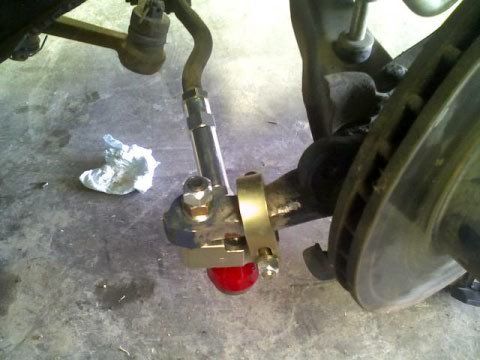
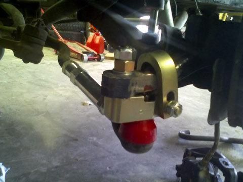
Got a little bit of work in over the weekend. Started mocking up and fitting the bump steer kit as well as the billet tie rod adjusters.
Pro-Motorsports Bump Steer/Steering Quickener Kit
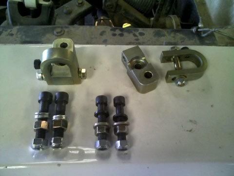
I'm using Versallies Spindles for now and they take a 1/2" tie rod compared to a Mustang 7/16" tie rod. I'm drilling out the holes in the spacer blocks that line up to the spindle steering arm and using 1/2" hardware. Once I get the Wilwood brakes and go back to the original Mustang spindle, I'll drill out the steering arm hole in the spindle to 1/2" and I'll be good to go. The 1/2" hardware is on the left. 7/16" hardware on the right.
The spindle steering arm required some clearancing to fit the steel strap over it.
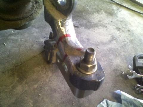
The strap finally slips over now I have to make sure there is enough clearance to bolt in place.
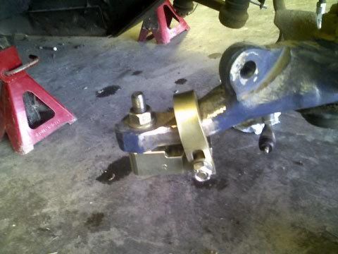
Clearanced and fitted
I didn't get around to drilling out the bocks for 1/2" bolts beause whatever material these blocks are made of is tough! Went through two 1/2" drill bits on my drill press and didn't even come close! Of course, I have a crappy drill press.
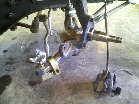
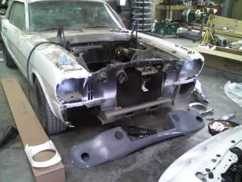
Also started mocking up the R-Model apron but it needs a lot of work to go on.
Pro-Motorsports Bump Steer/Steering Quickener Kit
I'm using Versallies Spindles for now and they take a 1/2" tie rod compared to a Mustang 7/16" tie rod. I'm drilling out the holes in the spacer blocks that line up to the spindle steering arm and using 1/2" hardware. Once I get the Wilwood brakes and go back to the original Mustang spindle, I'll drill out the steering arm hole in the spindle to 1/2" and I'll be good to go. The 1/2" hardware is on the left. 7/16" hardware on the right.
The spindle steering arm required some clearancing to fit the steel strap over it.
The strap finally slips over now I have to make sure there is enough clearance to bolt in place.
Clearanced and fitted
I didn't get around to drilling out the bocks for 1/2" bolts beause whatever material these blocks are made of is tough! Went through two 1/2" drill bits on my drill press and didn't even come close! Of course, I have a crappy drill press.
Also started mocking up the R-Model apron but it needs a lot of work to go on.
03-03-2009, 08:55 PM
#15
3rd Gear Member
Thread Starter
Join Date: Jul 2005
Location: El Paso, TX
Posts: 630
Took the spacer blocks down to a machine shop and had them drilled. My buddy who works at the machine shop said whatever these things are made of is harder than hell! Finally got every together and I even found some poly tie rod dust boots at Autozone so I bought a pair for the outer rods and a pair for the inner rods. Repacked all the bearings with fresh grease as well.
03-25-2009, 04:31 PM
#17
3rd Gear Member
Thread Starter
Join Date: Jul 2005
Location: El Paso, TX
Posts: 630
Got some work in over spring break.
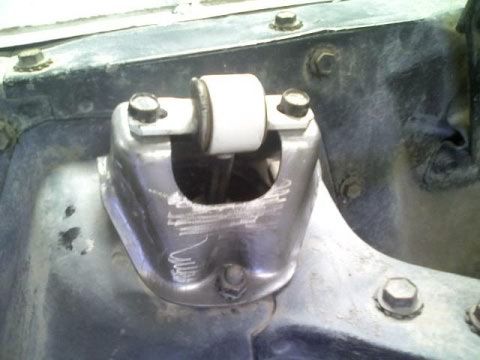
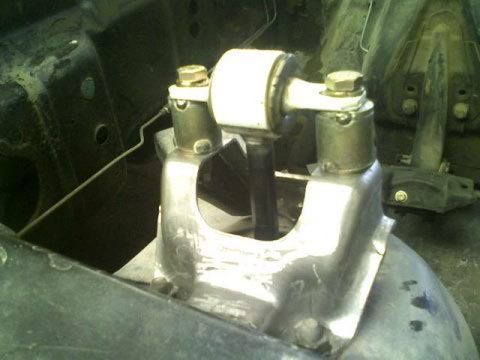
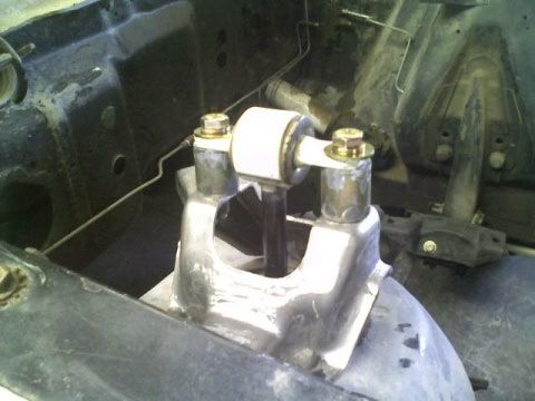
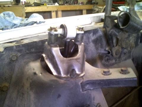
I came to the conclusion that since my car sits so low I have extremely limited available upward shock travel. I measured it to be approx. 1 3/4" and I ran the risk of bottoming out the shock and blowing it. I was looking for different ways to increase my available upward travel and though about raising the shock tower cap. I designed a spacer that would fit under the cap but when I got prices for actually making it, I found a temporary fix until I get new taller coils. I had a hell of a time finding aluminum spacers in the size I needed so I decided to make some out of steel sleeve and washers. What I like about doing this is that it also limits my suspension droop so the car will be responding a little bit faster on turn-in which should come in useful during autocross.
Before
After
03-25-2009, 04:32 PM
#18
3rd Gear Member
Thread Starter
Join Date: Jul 2005
Location: El Paso, TX
Posts: 630
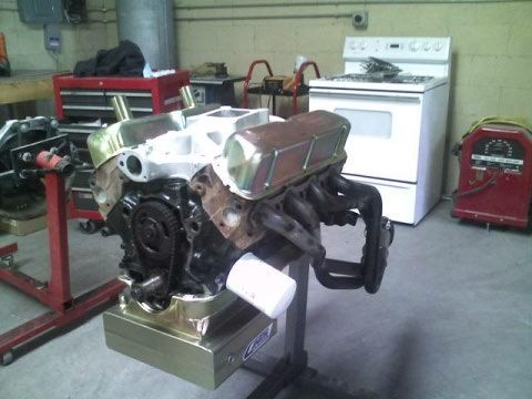
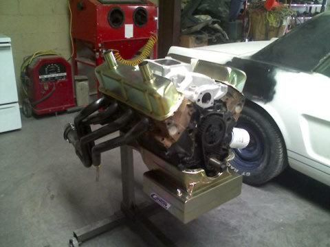
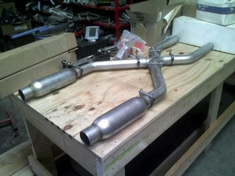
Also started mocking up the motor together to make sure I was going to like my oil pan and valve cover combo and see if my headers will have enough clearance for the clutch cable conversion. As well as test fitting the X-Pipe and Race Bullets so that I can see what additional bends I will be needing. I have a long way to go.