1966 Mustang Turn signal wire locations
 05-20-2012, 07:55 PM
#1
Thread Starter

Join Date: Sep 2010
Location: New York
Posts: 9
Hi Everybody,
So I replaced the turn signal in the steering column, but I did not write down
the color codes for the wires to go back into the plastic connector. I have looked at a lot of diagrams and it still confuses me. Does anyone out there have a good picture or could tell me the order of the 6 Pins ? I pretty sure the 2 pin connector is hooked up OK.
Thanks
Mike66
 05-22-2012, 03:09 PM
#2
4th Gear Member
Join Date: Jun 2006
Location: Fontana, California
Posts: 1,483
Hi Everybody,
So I replaced the turn signal in the steering column, but I did not write down
the color codes for the wires to go back into the plastic connector. I have looked at a lot of diagrams and it still confuses me. Does anyone out there have a good picture or could tell me the order of the 6 Pins ? I pretty sure the 2 pin connector is hooked up OK.
Thanks
Mike66
So I replaced the turn signal in the steering column, but I did not write down
the color codes for the wires to go back into the plastic connector. I have looked at a lot of diagrams and it still confuses me. Does anyone out there have a good picture or could tell me the order of the 6 Pins ? I pretty sure the 2 pin connector is hooked up OK.
Thanks
Mike66
yellow to yellow
yel-blu to yel-blu
Green to Green
Grn-wht to Grn-wht
Blue to Blue
Wht-blu to Wht-blu
The order in the plug doesn't matter just connection to the mating side.
05-22-2012, 06:09 PM
#3
Thread Starter
Join Date: Sep 2010
Location: New York
Posts: 9
Thanks for the info - the problem I have with the wires being plugged in to the connector the way I think It should be is my horn will work but when I use the turn signal nothing happens. An interesting think is when I turn ny light switch to half way out the parking light come on. When I pull the switch all the way out the headlights come on and the parking lights go out.. I can't think this is normal !! I been looking over the Ford Electrical Book trying to trace all the connections but it is driving me nuts.. It is probably something simple I am missing. Any help or suggestions would be helpful
05-23-2012, 05:25 AM
#4
6th Gear Member

Join Date: May 2009
Location: PA
Posts: 5,232
An interesting thin is when I turn ny light switch to half way out the parking light come on. When I pull the switch all the way out the headlights come on and the parking lights go out.. I can't think this is normal !! I been looking over the Ford Electrical Book trying to trace all the connections but it is driving me nuts.. It is probably something simple I am missing. Any help or suggestions would be helpful
Early logic was a car is either parked or driving, but not both. Later, they decided it would be safer if cars were lit up like a Christmas tree.
05-23-2012, 02:36 PM
#5
4th Gear Member
Join Date: Jun 2006
Location: Fontana, California
Posts: 1,483
2+2 is right on it- early cars didn't have both parking and running lights together like we have today . On your other comment, the turn signal gets its power from directly the flasher which is supplied by the blue wire into the switch. Start there with a DVM and check for power.
05-23-2012, 07:16 PM
#7
Thread Starter
Join Date: Sep 2010
Location: New York
Posts: 9
I hooked up the new flasher and I discovered that someone had the wires wrong on the old flasher and it semi melted the wires outer insulator together... I seperated the wires and they appear not to be damaged. I hooked a volt metter to the blue wire going into the flasher and get no reading. I think I checked it correctly but I not that strong with the metter. I also checked the wire diagram it it looks like when the wires leave the flasher the blue goes to the ignition switch? Any suggestions
05-24-2012, 02:28 PM
#8
4th Gear Member
Join Date: Jun 2006
Location: Fontana, California
Posts: 1,483
The blue wire is the flasher output and it goes to the TS switch. The other wire should be yellow and it goes to a junction point in the harness that is connected to the ign switches' Black Green wire. check for voltage at the yellow wire if it's not there you need to go to the Ign switch middle connector (A)
05-25-2012, 05:09 PM
#9
Thread Starter
Join Date: Sep 2010
Location: New York
Posts: 9
here is maybe a good question, In looking at the diagrams it looks the a wire from the flasher needs to be hooked up to the back of the ignition switch post. Right now all thats hooked to this post is the wire for the radio.... I put a volt meter on the horn buttons and have power there. I don't believe the wires from the steering column are the problem, could it be whats written above?
05-29-2012, 03:12 PM
#10
4th Gear Member
Join Date: Jun 2006
Location: Fontana, California
Posts: 1,483
here is the diagram. Ill walk you thru it.
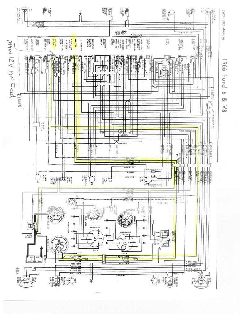
No the horn power is from another source. There should be 4 wires hooked to the back of the Ign switch. There is 1 wire off of the center of the ign switch that powers quite a few things-that wire is black and green. It only becomes energized with the ign "ON" (which is also a good spot to hook an aftermarket radio wire). If you follow this wire into the harness it connects at a "dot". this dot is where your 12v comes from to run the flasher- the wire is yellow. on the other side of the flasher is blue wire this is the main "hot" wire that goes to the turn signal switch.
No the horn power is from another source. There should be 4 wires hooked to the back of the Ign switch. There is 1 wire off of the center of the ign switch that powers quite a few things-that wire is black and green. It only becomes energized with the ign "ON" (which is also a good spot to hook an aftermarket radio wire). If you follow this wire into the harness it connects at a "dot". this dot is where your 12v comes from to run the flasher- the wire is yellow. on the other side of the flasher is blue wire this is the main "hot" wire that goes to the turn signal switch.