
DIY adding air to air to my Kenne Bell on a 92 coupe


Thread Starter
1st Gear Member
Joined: Sep 2008
Posts: 108
From: Maine
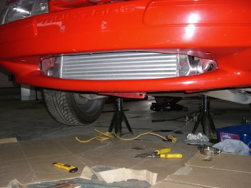
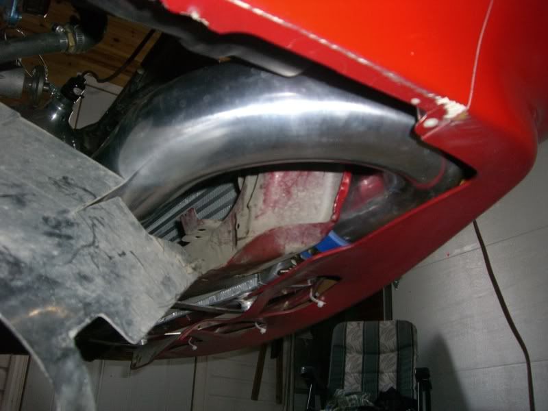
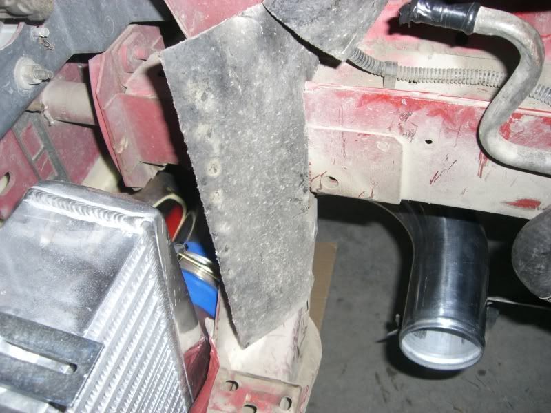
Did some work today on the lower lip of the front bumper. I'm gonna try and mount the I/C as low as possible to get max cooling from the opening. I also worked on a block off plate for the intake side of the bypass. I used a sheet of Aluminum and but the piece to size with my radial arm saw and yes no special blade needed a regular carbide blade cuts great if you go slow. I shaped the piece using my metal cutting blade on my chop saw. A little sanding with 600 grit then hit it with my polishing wheel and looks great.
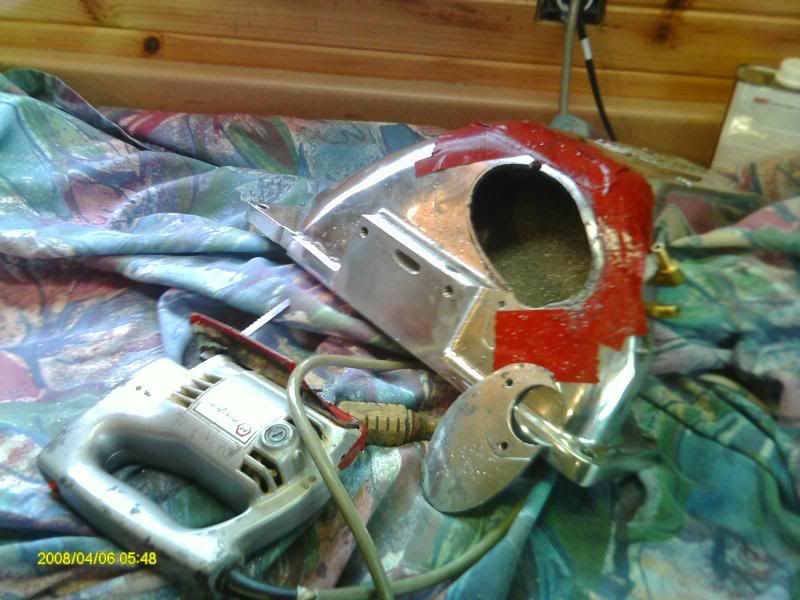
Here is where I clearanced the inside of the front bumper cover to clear the 3" pipe.

3" pipe inside the bottom of the bumper cover.
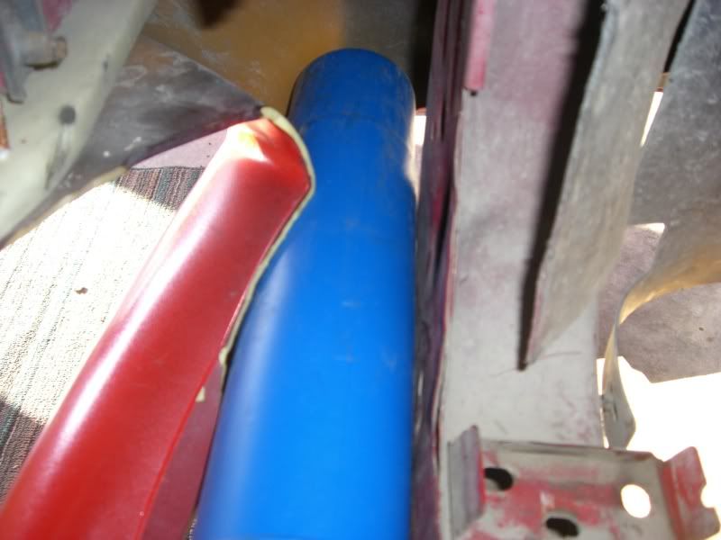
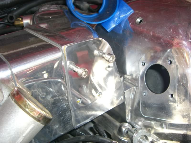
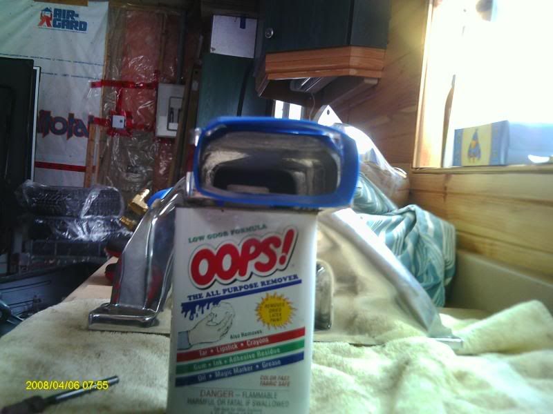
Here is the plate I made to block off the bypass inlet. I will try and fab up the bypass later, but for now I'll block it off.
Here is where I clearanced the inside of the front bumper cover to clear the 3" pipe.
3" pipe inside the bottom of the bumper cover.
Here is the plate I made to block off the bypass inlet. I will try and fab up the bypass later, but for now I'll block it off.
Thread Starter
1st Gear Member
Joined: Sep 2008
Posts: 108
From: Maine
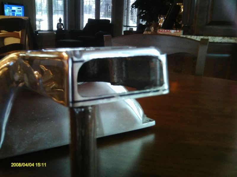
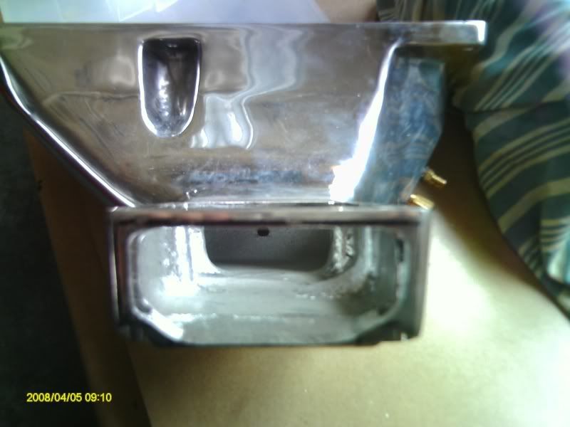
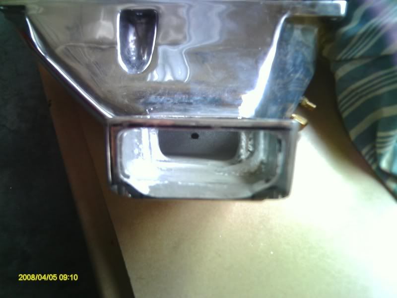
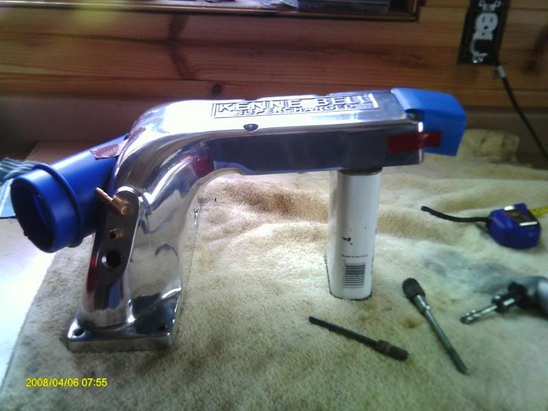
Last night the KB came off in preparation for the fabrication and welding work. I seperated the 2 pieces and cleaned the gasket gunk off. I was very surprised how light those 2 pieces are, its the blower case and drive that are hefty. I started openning up at the end of the discharge manifold by first drawing my my lines 1 1/4 by 3 1/4 of material inside to come out. The bottom lip that mates to the blower case I left 1/4 in and the top is opened to the roof of the intake. I also went deep into the sides where the bolt holes are and cut out almost all of the extra material around the bolt hole. I'm not worried as these bolts don't see much torque and some sealer there will stop any leaks. I used my drill to puncture about 20 holes around the perimeter and then a medal blade on my elec jig saw. Finished up the hole with air tools and carbide bit for aluminum. Looks real nice and should be big enough opening to support the 3 inch pipe. So my plans to cut part of the top out as shown in my mock up plans is on hold. I'll try and get some pics up soon, wife went on business and stole the camers :-(
__________________
92 stock block & cam, KB 2.1 Big Bore kit, Flow/Blow 12.5 psi, water/meth injection dual nozzle 21 gph, Tmoss ported lower, TW heads, 60 lb injectors, 95mm PMAS Velocity MAF, custom 4" intake, 90mm T/B, 255lph HP intank, FP stock, Crane HI-6R, SCT tune by LaSota racing and Zeitronix wideband.
Thread Starter
1st Gear Member
Joined: Sep 2008
Posts: 108
From: Maine
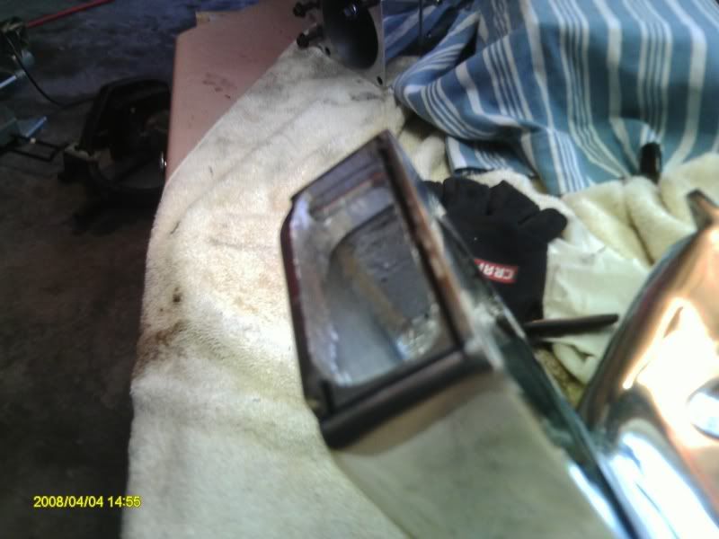
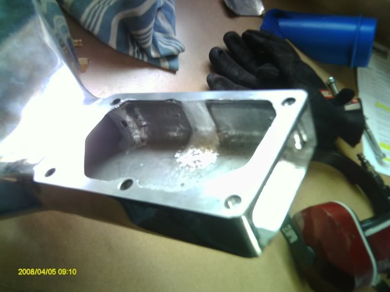
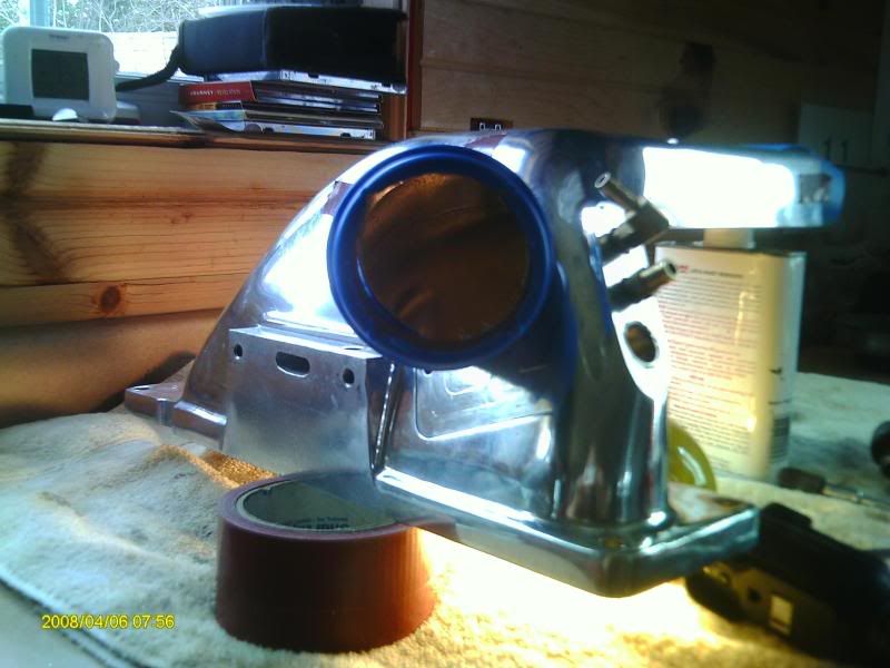
Did some more porting and opening up the discharge end this morning. The bolts going through really choked it out again so I took out more on the roof section. Also cut out the solid chunk in the middle section and smoothed it out should flow very nice now.
Last edited by roh92cp; Apr 20, 2009 at 05:50 AM.
Thread Starter
1st Gear Member
Joined: Sep 2008
Posts: 108
From: Maine
Worked on the discharge today, used my small jig saw again with a metal blade. Found out that it cuts much better with WD-40, otherwise the blade clogs up. Smoothed it out with carbide cutting burr. Welder is coming over today to take a look at the job so I'm hoping the Pipe will be in by Thursday and I can get started cutting and shapping the ends to be welded on the intakes.
Thread Starter
1st Gear Member
Joined: Sep 2008
Posts: 108
From: Maine
The project is delayed for another week damit. The 3" pipe kit I ordered never got shipped due to the supplier running out of straight pipe. I won't see it till middle of next week. The intercooler and 2.75 inch pipe will be in Wenesday so I'll have that to work on, and I'll get some pics up. The welder came by and said there no problem with welding job he said TIG welding can support thinner metal welding. He said it would take about 2 hours of his time. I'm getting antsy waiting for the pipe. I'm gonna have to repolish my blower case and manifolds after all this, as all the cutting moving it around and metal shaving have scratch the hell out of the polished surface. Should have kept it anodized black, but I got the full polished upgrade for free so what the hell.
Thread Starter
1st Gear Member
Joined: Sep 2008
Posts: 108
From: Maine
Here is a link to the Intercooler kit and pipe I ordered off Ebay.
http://cgi.ebay.com/ebaymotors/ws/eB...3AIT&viewitem=
http://cgi.ebay.com/ebaymotors/ws/eB...3AIT&viewitem=
http://cgi.ebay.com/ebaymotors/ws/eB...3AIT&viewitem=
http://cgi.ebay.com/ebaymotors/ws/eB...3AIT&viewitem=
Thread Starter
1st Gear Member
Joined: Sep 2008
Posts: 108
From: Maine
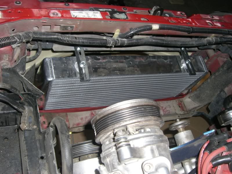
Very nice got the Intercooler and 2.75 inch pipe kit today and I must say CXracing has great deal The value for $$$ is there. The intercooler is huge I can't believe it looked like a 4". Its 31x12x3 very nice and polished the pipe is as ordered polished with rolled lip. Silicone couplers are 3 ply and clamps are high qaulity staneless and heavey duty. Got the IC intalled and bolted in fits very nice. I will have to trim more of the mouth ends to fit the pipe and coupler in.
Thread Starter
1st Gear Member
Joined: Sep 2008
Posts: 108
From: Maine
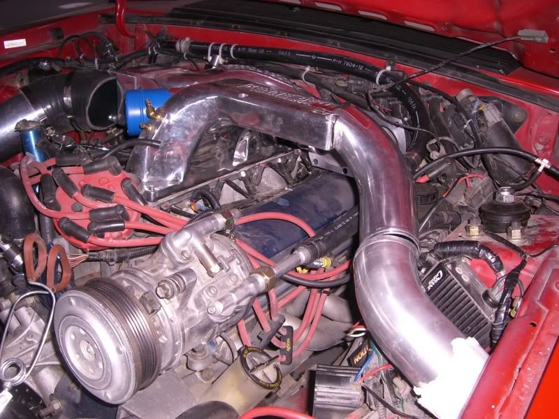
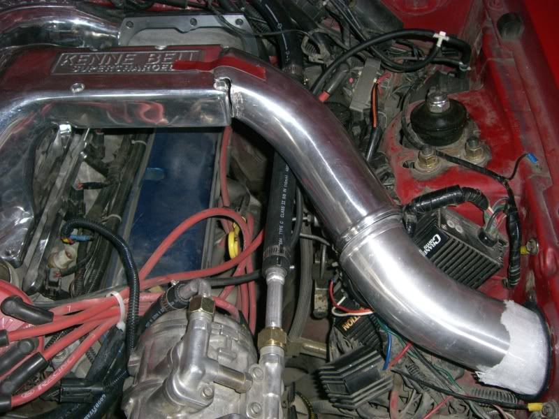
Got the 3" pipe kit today from CXracing. I was very pleased with how well things went. I mostly worked on the drivers side I started at the IC with a 90 deg L and then went with another 90 L up towards the top of the fender panel. Lucky I orders and S bend, because it fit perfect and made the turn out the fender hole where the windshield tank use to go. I had a 45 degree silicone to join the S bend and the 90 L, fit perfect. I then spent about 2 1/2 hours cutting hammering and bending and shapping the small piece from the KB manifold end to the S pipe. It fits great and should look good. I used a U pipe from the passenger side IC to just inside the frame rail. I'll finish that up tomorrow. Here are some pics of my progress.
[IMG]http://i25.photobucket.com/albums/c70/roh92cp/KBintercooler036.jpg
[/IMG]
The pipe connecting to the manifold had to be flatened and sqaured and cut on 2 angles to fit, took alot of work but fits nice.
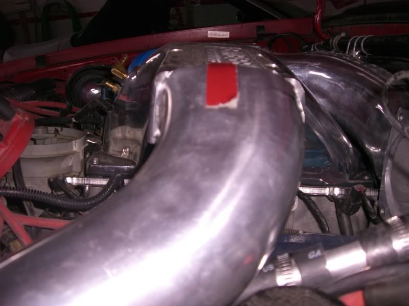
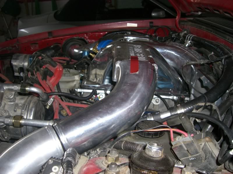
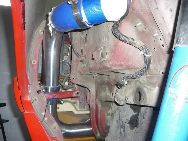

Passenger side U bend.
[IMG]http://i25.photobucket.com/albums/c70/roh92cp/KBintercooler036.jpg
[/IMG]
The pipe connecting to the manifold had to be flatened and sqaured and cut on 2 angles to fit, took alot of work but fits nice.
Passenger side U bend.
Thread Starter
1st Gear Member
Joined: Sep 2008
Posts: 108
From: Maine
Quote:
Originally Posted by mark007
coming along very nicely. remember smooth trasitions are in your best interest. hard bends will slow things down abit.
Yes I was very much concerned with that also. I tried to improve are flow from Mikes design. He admitted his 2.5 inch pipe and the exit and inlet into the KB manifold were to small. The 3 inch pipe really was not hard to fit with a little caoxing from saw and grinder. If you compare my exit pipe driver side to Mikes I used a 45 degree angle to his 90 which reduced 1 bend and of course not as steep. Also the end of the pipe to be welded the the manifold has a smoother bend and has much more area to flow. I Will also use 45 degee angle at the discharge side. I may be able to get things welded up by Friday if all goes well.