
DIY Brake Cooling Duct Fabrication

Thread Starter
3rd Gear Member
Joined: Jan 2006
Posts: 757
From: Chicago
This is how I made my own complete brake duct kit for less than $80. I thought I would share my experiences for those interested in doing something similar. Hopefully some of this helps others. At the end I have a price list and suggestions for alternatives. In this post I�ve only given the shortest �title� and brief explanations to each step, omitting a full explanation of the steps taken. If anyone is really interested in doing this on their own, I can provide the complete write up I did (it is really long and more detailed than most probably care to witness).
Best,
-j
Basic Theory:
The function of brake ducts is fairly simple; pump cool air into the rotors. The benefit is to combat the high heat buildup experienced during high performance driving. On the street, I see little benefit, as there is typically ample time for the rotors to cool down between aggressive braking (such as in an emergency situation). If you are braking aggressively enough on the street to genuinely need brake ducts, please turn yourself into the authorities; stop reading now and go.
On a road course (this typically would not include autocross), the rotors and pads build up very high heat over the course of a few sessions (say, by the second or third 15-20 minute session). On our cars (like most) the rotors are vaned to pump air from their center out to their edge. So this means you need to get the cool air as close to the center as possible. The closer your duct outlet is to the face of the rotor center, the better the benefit. To do this you need a rigid and reliable way to mount the duct hose so that it is pointed into the center. The inlet of the duct should come from a source of cool ambient air, and the hose should be routed as far away from heat sources as possible.
Design Objectives:
1. Keep cost low. At the time of my work the cheapest cooling duct kit I found was in the range of $150, and it didn�t come with hose or bumper inlets. Many existing kits are like this, and factoring in those that also offer inlets for sale bumped the price as high as $500. Recently I�ve seen FRPP�s full kit (bumper inlets, hose, and spindle mounts, Model: M-2004-A) on sale for $365, which isn�t half bad. Still, you can build your own for a third of that price.
2. To aid in #1, use as much existing hardware as possible. Aside from cost, the benefit is that you don�t have to worry about things fitting properly, since they were already designed from Ford to fit the car. I used/modified the following OEM parts: bumper, lower bumper grill, brake dust shields.
3. To aid in #1, I used as much raw material as I currently had lying around. This is where cost becomes a fluid topic. I like to play with composites, so I have quite a bit of extra fiberglass mat, epoxy, fillers, and tools with which to work on such projects just lying around. This means that for some the cost will rise, however I have tried to indicate affordable alternatives. So the total cost shouldn�t be much more than it was for me.
4. Inlet should be aerodynamically and aesthetically sound. I�ve seen some kits come with inlets that simply open at the same diameter as the hose (3�) with no funneling in or gradual taper down to the hose size. This limits the amount of air taken in, and often results in an awkward appearance. As much as possible I wanted the inlets to appear �designed� rather than �riveted on.� I�m not opposed to a �race� look, only to a �let�s just stick it here� look. I also wanted the inlet to use the existing lower grill ends to look like it came from Ford that way.
5. Durability. I�ve seen folks use a variety of hose materials, and most are inappropriate. They might look cool immediately after installation, but shortly after they�re cracked or melted and then they neither work nor look cool. So I opted to use actual high-temp air duct hose. You can get a 6 foot length (more than you�ll need) of this stuff from Pegasus Auto Racing Supplies for $55 plus shipping. Alternatively, you can hunt around eBay for a lightly used batch for about the same price. I picked up a bunch of it for very little money, and for my use the supply should last a very long time even if I go through a set a year (I don�t expect this to happen, but it gives you an idea of the value). To me this seems far more sensible than trying to make aluminum duct or plastic air duct work. That stuff isn�t made for the heat, wear, and vibration that they�ll be subject to in a high performance driving environment. At such prices as can be found, why not use the right stuff?
6. Finally, they need to function. Since this isn�t rocket science, the order of the day is to attend to the basic theory and build it sound. Make sure when planning your hose routing that you�re not rubbing on anything, and that you can clock your wheels from side to side without pulling the hose off or inducing interference somewhere else.
I'll put the execution in subsequent posts.
Thread Starter
3rd Gear Member
Joined: Jan 2006
Posts: 757
From: Chicago
Execution: (I hope that I can get the images to imbed properly, otherwise you�ll have to scroll down to see the images.)
1. Remove lower grill.
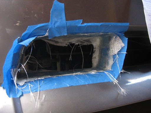
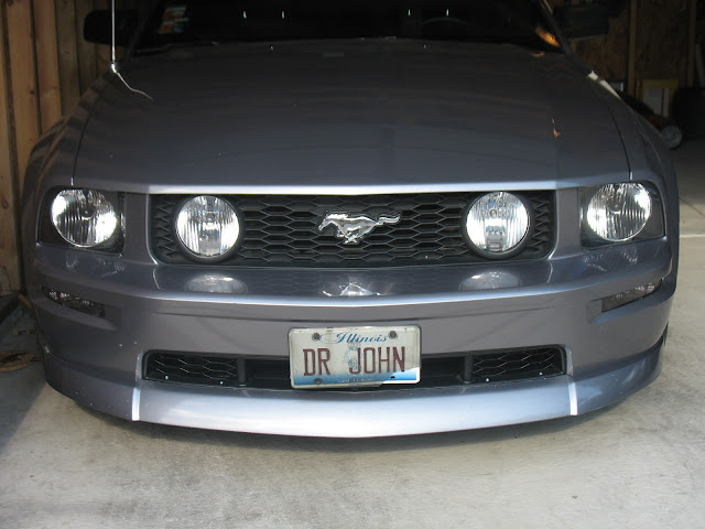
2. Cut OEM bumper backing for grill. The black plastic grill is non-functional, and so the OEM bumper has a fully blocked back that acts as the support for the grill clips. You need to remove this in order to get air through the bumper. Don�t worry, this is much easier than you think, and whatever cutting you do will be completely covered once you put the grill back in place. I actually used an X-acto knife to do it. The bumper is a fairly soft plastic that cuts easily; I started with a utility blade for the straight sections but switched to the knife for the curved parts. You can literally stitch out the section by just pressing in the blade, remove/reposition it, press in, remove/reposition, move on, etc. Follow the perimeter of the area covered by the grill, just the backing part (see pic #1).
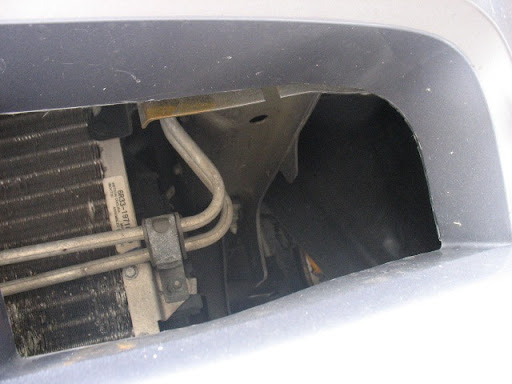
A bit of patience is all it takes and you�ll do a better job than you might imagine. I�m sure others will think of better ways to cut the bumper, but this was easy and available to me.
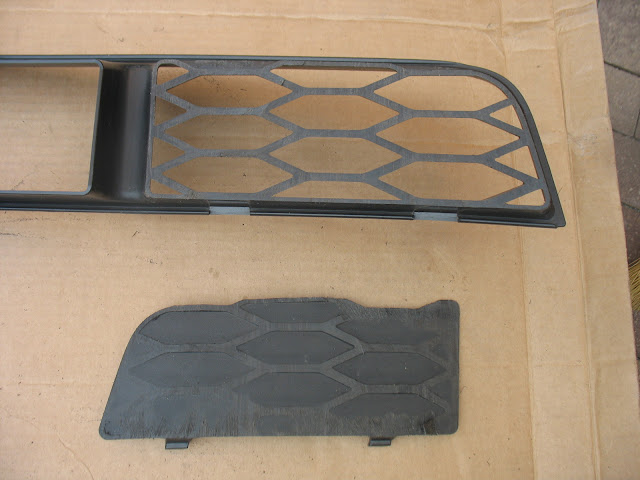
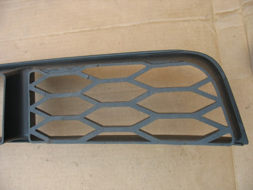
3. Prep the lower grill. I wanted to keep the OEM grill bars and only remove the plastic that blocks airflow. Get yourself a coping saw (min. 4-3/4� depth cut) and carefully slice off the back of the grill. You only need to remove about 1/16� or so of material, so stay close to the edge. You�ll actually be able to see the blade just clear the backing, yet leave the grill bars intact.

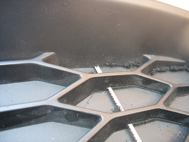
There will be enough of the bars to remain quite strong. If you go slowly, you�ll end up with a finely finished piece on the first try.
4. Drill new mounting points. You can simply drill the ends in four points (two top, two bottom) and use screws or bolts of your liking.
1. Remove lower grill.
2. Cut OEM bumper backing for grill. The black plastic grill is non-functional, and so the OEM bumper has a fully blocked back that acts as the support for the grill clips. You need to remove this in order to get air through the bumper. Don�t worry, this is much easier than you think, and whatever cutting you do will be completely covered once you put the grill back in place. I actually used an X-acto knife to do it. The bumper is a fairly soft plastic that cuts easily; I started with a utility blade for the straight sections but switched to the knife for the curved parts. You can literally stitch out the section by just pressing in the blade, remove/reposition it, press in, remove/reposition, move on, etc. Follow the perimeter of the area covered by the grill, just the backing part (see pic #1).
A bit of patience is all it takes and you�ll do a better job than you might imagine. I�m sure others will think of better ways to cut the bumper, but this was easy and available to me.
3. Prep the lower grill. I wanted to keep the OEM grill bars and only remove the plastic that blocks airflow. Get yourself a coping saw (min. 4-3/4� depth cut) and carefully slice off the back of the grill. You only need to remove about 1/16� or so of material, so stay close to the edge. You�ll actually be able to see the blade just clear the backing, yet leave the grill bars intact.
There will be enough of the bars to remain quite strong. If you go slowly, you�ll end up with a finely finished piece on the first try.
4. Drill new mounting points. You can simply drill the ends in four points (two top, two bottom) and use screws or bolts of your liking.
Last edited by Philostang; Feb 11, 2010 at 01:33 PM.
Thread Starter
3rd Gear Member
Joined: Jan 2006
Posts: 757
From: Chicago
5. Molding the inlets to fit the OEM bumper. Now the real fun begins! There�s at least two ways you can do it; my way and the right way. Yeah, you learn from doing things the long way that you could have saved a ton of grief if you had only done a few things differently. I used a fiberglass technique known to me as making a foundation mold. This is done by first masking off the area you want molded with at least two layers of tape. Then you spray a bit of adhesive to help the fiberglass stick in place, lay the glass down, and then wet it out with your resin.
I prefer epoxy resins for their greatly enhanced strength over polyester resins (common Bondo stuff). However, for this project I don�t think there�s really much wrong with using the polyester stuff. This isn�t a serious structural part, but it does need to be fairly stiff. At any rate, once your resin dries you pop it off the car, trim, and wallah!�you have an exact duplicate of your car that you can now use to build off of. In retrospect this wasn�t necessary. I know. Live and learn. A much more sensible approach would have been to simply tape off the GRILL and mold directly from there. The grill is removed from the car, it can be positioned anywhere, walked around, etc., etc. That makes so much more sense, but hey, that�s life. If you do the grill version I would advise you to refrain from drilling your mounting points until after your ducts are finished and mocked up to the car. They may add thickness to the back of the grill, making it sit in a slightly different position than they did when on the car alone. Drill into the bumper only when both the ducts and the grill are in position.
6. Forming the duct inlet bucks from foam. The foam I used was a piece of 4� thick floral foam you can find at most craft shops. This is very easy to cut and sand to your liking, making sure it fits your mold or the grill perimeter.
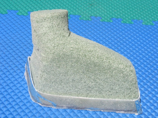
You can make the basic shape/taper just about any way you want, but you do need to pay attention to the clearance out back. I found that on the passenger side you have to make sure you can mount the hose to the duct while clearing some of the small hard tubes near the radiator. This meant that the buck�s outlet needed to be angled down (compared to the driver side).
The driver side has plenty of room for the duct. Tape up the buck and wax as a release agent.
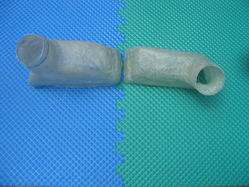
7. Lay up duct inlet. This is standard fiberglass wet lay up work.
8. Remove foam buck.
9. Paint with black bumper paint.
10. Mock up inlet fit with bumper and grill, and mark for drilling. Remove the mock up, and drill the bumper. Now you are ready to mount everything.
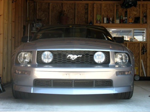
I originally thought I needed to get slick with bolts and nuts, etc. Then I remembered the way the license plate screws into the bumper. So I just went with very coarse thread screws. After several thousand miles I have seen no indication that they won�t hold indefinitely.
I prefer epoxy resins for their greatly enhanced strength over polyester resins (common Bondo stuff). However, for this project I don�t think there�s really much wrong with using the polyester stuff. This isn�t a serious structural part, but it does need to be fairly stiff. At any rate, once your resin dries you pop it off the car, trim, and wallah!�you have an exact duplicate of your car that you can now use to build off of. In retrospect this wasn�t necessary. I know. Live and learn. A much more sensible approach would have been to simply tape off the GRILL and mold directly from there. The grill is removed from the car, it can be positioned anywhere, walked around, etc., etc. That makes so much more sense, but hey, that�s life. If you do the grill version I would advise you to refrain from drilling your mounting points until after your ducts are finished and mocked up to the car. They may add thickness to the back of the grill, making it sit in a slightly different position than they did when on the car alone. Drill into the bumper only when both the ducts and the grill are in position.
6. Forming the duct inlet bucks from foam. The foam I used was a piece of 4� thick floral foam you can find at most craft shops. This is very easy to cut and sand to your liking, making sure it fits your mold or the grill perimeter.
You can make the basic shape/taper just about any way you want, but you do need to pay attention to the clearance out back. I found that on the passenger side you have to make sure you can mount the hose to the duct while clearing some of the small hard tubes near the radiator. This meant that the buck�s outlet needed to be angled down (compared to the driver side).
The driver side has plenty of room for the duct. Tape up the buck and wax as a release agent.
7. Lay up duct inlet. This is standard fiberglass wet lay up work.
8. Remove foam buck.
9. Paint with black bumper paint.
10. Mock up inlet fit with bumper and grill, and mark for drilling. Remove the mock up, and drill the bumper. Now you are ready to mount everything.
I originally thought I needed to get slick with bolts and nuts, etc. Then I remembered the way the license plate screws into the bumper. So I just went with very coarse thread screws. After several thousand miles I have seen no indication that they won�t hold indefinitely.
Last edited by Philostang; Feb 11, 2010 at 01:35 PM.
Thread Starter
3rd Gear Member
Joined: Jan 2006
Posts: 757
From: Chicago
Outlet Side:
11. Slice tubes lengthwise to ensure fit with 3� hose. If you just get the ride diameter tube, this step is entirely unnecessary. The exhaust tube I got was 3� inner diameter tube (my local auto parts store was out of the 3� outer diameter tube, which would have been the right side). If you must work with the larger tubing, just slice out a �� segment longitudinally from the tube. When you squeeze it together you should have about a 3� outer diameter tube. Weld it back together, and you�re done.
12. Cut outlet holes in dust shields. Cut small here, but close to a 3� diameter. You can finesse the opening later after the tube is tacked in place.
13. Cut exhaust tube to length and form to dust shield.
I started with a short 3� to 4� piece and simply halved it. You don�t need much, just enough to get a solid grip on the hose. Once you have the two sides, you need to cut one end to conform to the dust shields.
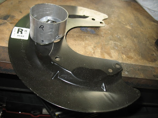
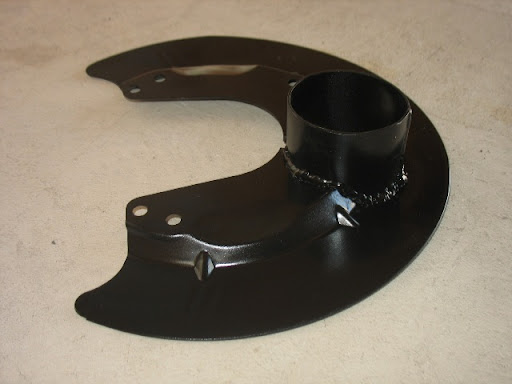
14. Weld tubes to shields.
Take your time to get the shape nice and accurate, and you will be rewarded with a quick and easy weld job. Also, if you don�t have a welder, this is a good way to keep cost down when you bring it to a welding shop. The less they have to do in fitting the tube to the shield, the less you�ll pay in labor. If you bring everything in ready to weld, all they have to do is a quick 20 minute job (if that). So make it neat and tight. I didn�t do this. So, not surprisingly my weld job was a mess and looks awful. Fortunately, nobody is ever going to see it, and it functions perfectly so there�s only a loss of pride in a job poorly done.
15. Paint shields with brake caliper paint.
I choose brake caliper paint because it has a high heat resistance and the shields will absorb quite a bit of heat from the spindles. I choose black because I wanted things to disappear in the background.
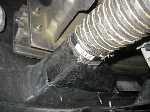
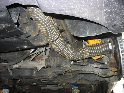
16. Assemble all parts and route/secure hose.
Not much to add here, except be sure to test run your routing by turning your wheel from lock to lock.
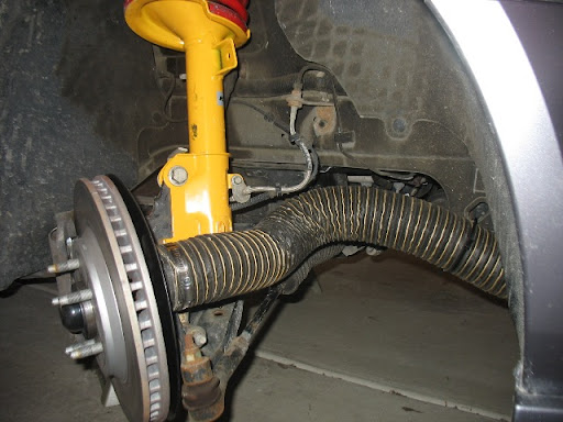
Make sure it doesn�t rub or pull excessively on anything. You don�t want your hose stressed any more than it will be under regular use.
11. Slice tubes lengthwise to ensure fit with 3� hose. If you just get the ride diameter tube, this step is entirely unnecessary. The exhaust tube I got was 3� inner diameter tube (my local auto parts store was out of the 3� outer diameter tube, which would have been the right side). If you must work with the larger tubing, just slice out a �� segment longitudinally from the tube. When you squeeze it together you should have about a 3� outer diameter tube. Weld it back together, and you�re done.
12. Cut outlet holes in dust shields. Cut small here, but close to a 3� diameter. You can finesse the opening later after the tube is tacked in place.
13. Cut exhaust tube to length and form to dust shield.
I started with a short 3� to 4� piece and simply halved it. You don�t need much, just enough to get a solid grip on the hose. Once you have the two sides, you need to cut one end to conform to the dust shields.
14. Weld tubes to shields.
Take your time to get the shape nice and accurate, and you will be rewarded with a quick and easy weld job. Also, if you don�t have a welder, this is a good way to keep cost down when you bring it to a welding shop. The less they have to do in fitting the tube to the shield, the less you�ll pay in labor. If you bring everything in ready to weld, all they have to do is a quick 20 minute job (if that). So make it neat and tight. I didn�t do this. So, not surprisingly my weld job was a mess and looks awful. Fortunately, nobody is ever going to see it, and it functions perfectly so there�s only a loss of pride in a job poorly done.
15. Paint shields with brake caliper paint.
I choose brake caliper paint because it has a high heat resistance and the shields will absorb quite a bit of heat from the spindles. I choose black because I wanted things to disappear in the background.
16. Assemble all parts and route/secure hose.
Not much to add here, except be sure to test run your routing by turning your wheel from lock to lock.
Make sure it doesn�t rub or pull excessively on anything. You don�t want your hose stressed any more than it will be under regular use.
Last edited by Philostang; Feb 11, 2010 at 01:36 PM.
Thread Starter
3rd Gear Member
Joined: Jan 2006
Posts: 757
From: Chicago
Evaluation:
I�ve had the ducts on for two track day events. I�ve been very pleased with them, as they have held up well and were very easy to use. I take the front of the hoses off during normal summer use, and then I put them back on at the track. Back to back comparison is tough, so I can�t say how much they have saved my rotors and pads, but I figure the system can only be helping. I will say that the back of my rotors are noticeably cleaner than the outer face. I�m not sure how much, if any, of that can be attributed to the brake ducts.
After installing them initially I left them on and discovered that on long trips (especially at night) they have a tendency to suck up bugs. These little critters are drawn into the rotor and then spit out onto the insides of your wheels. Ugly. So I found it was quite easy to reach up under the bumper with a small ratchet and remove the clamps/hose from the inlet (w/o jacking the car up). I could then tuck the hose into the bumper and they stay put through regular driving. Trust me, I put over 500 miles on the car with the hoses tucked into the bumper and had no problems with them ever dropping.
Now that my track season is over I have removed the hoses entirely. Given the location of the inlet and dust shield, I don�t see any reason to remove the rest of the system.
Parts Price List: I had many of the items on this list, and I used epoxy resin I already had (instead of the typical polyester resin found in an auto parts store kit). So my total cost was a bit over $75 for the entire system. The following is a rough approximation of what it would take to duplicate my effort if you had to get all the materials new. I also included the list of tools used, so for those without these the cost would go up appropriately. However, all of these tools are the sort that are useful for just about any fabrication job, so their cost can be distributed over many projects for as long as their service life permits. The big tool, of course, is the welder. If you don�t have one I can�t imagine a welding shop is going to charge you much to do the tube if you bring it in fully trimmed needing only to do the weld itself. Even if you didn�t, I wouldn�t be surprised if they would do the trimming as well for under $50 (but that�s a guess).
Supplies:
1. Bondo Fiberglass Repair Kit (incl. resin & cloth): $15
2. Blue Masking Tape: $2.50
3. Spray Adhesive: $2.50
4. 4�x16� Block of Floral Foam: $15
5. Exhaust Tube (3� o.d.): $5
6. PCV Tube (2� i.d.) or another piece of 3� o.d. exhaust tube: $5
7. High Temp Duct Tubing (6� length): $60
8. 3� Band Clamps (qty. 4): $5
9. Bumper Paint: $5
10. Brake Paint: $5
Total: $120
Tools:
1. Box of latex gloves (mandatory: you�ll hate yourself if you do this without them)
2. Coping Saw (minimum 4-3/4� depth of cut)
3. Sandpaper (assorted)
4. Heavy Scissors (for cutting fiberglass cloth)
5. X-acto Knife (for trimming bumper)
6. Utility Knife (for trimming bumper)
7. 4� Angle Grinder w/Cutting Blade
8. Welder
Thread Starter
3rd Gear Member
Joined: Jan 2006
Posts: 757
From: Chicago
Hey 157db,
Thanks.
They do make in-line cooling fans that you can just splice into the front duct, but that would have cost more and require more work wiring it in, etc. I figure that this is one of the great benefits of a cool down lap.
Best,
-j
Thanks.
They do make in-line cooling fans that you can just splice into the front duct, but that would have cost more and require more work wiring it in, etc. I figure that this is one of the great benefits of a cool down lap.
Best,
-j
4th Gear Member
Joined: Oct 2007
Posts: 1,778
From: Harrisburg PA
That is a great fabrication job, well done. I have the set up from Quantum Motorsports, cost a total of $250 which is considerably cheaper than the Ford brand, always a trade off - if you have the time, materials and know how I always love the DIY approach.
Like you said, brake ducts make a big difference. I got 13 track days out of one set of Hawk HT-10 pads when using ducts and they could have gone at least one more. Without ducts I could smell the pads cooking, with ducts no smell. The inside of the rotors, where the air hits doesn't heat check nearly as bad as the outside. Whether you buy them or fab them yourself they are an excellent investment.
Like you said, brake ducts make a big difference. I got 13 track days out of one set of Hawk HT-10 pads when using ducts and they could have gone at least one more. Without ducts I could smell the pads cooking, with ducts no smell. The inside of the rotors, where the air hits doesn't heat check nearly as bad as the outside. Whether you buy them or fab them yourself they are an excellent investment.
4th Gear Member
Joined: Feb 2008
Posts: 1,083
From: Buffalo, NY
Very nice work, if I had a real need for this I would do it in a second, but since I don't xcross, as you said probably won't seem much of a benefit. One thing I took away from your write up however is how easy it would be to improve the look of the lower grill my cutting away that backing of that honeycomb. Combined w/ the SHR lower grill insert would give a much more consistent look.