Help..2nd attemp at alternator warining light install.
 11-12-2011, 12:51 AM
#1
Moderator
Thread Starter
Join Date: Dec 2005
Location: Hills of California
Posts: 5,208
Hello
So im still wanting to build an alt warning indicator for my 66.
I think I almost have it figured out but could use some help on a bit of wiring.
Have a look at this diagram.
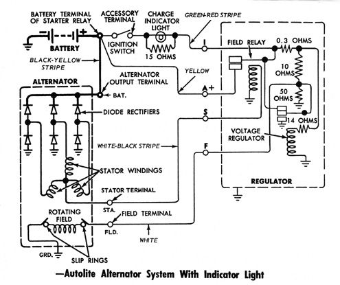
I am attempting to build the "charge indicator light"
It looks like I need to run a wire from the accessory ignition switch position to a light with a 15 Ohm shunt and finally to the I post on the regulator.
The question is
1) It looks like the acc terminal is the same thing as a "hot when ignition is on" 12v source. Rather than go through the trouble of trying to find the accessory wire shown do you think I could simply use any 12v source that is hot with ignition on?
2)any idea what color the accessory terminal wire is? Is it green + red stripe or is that for the charge indicator?
3) Any idea why the hell they would run a 15 ohm shunt?
Thanks
-Gun
So im still wanting to build an alt warning indicator for my 66.
I think I almost have it figured out but could use some help on a bit of wiring.
Have a look at this diagram.
I am attempting to build the "charge indicator light"
It looks like I need to run a wire from the accessory ignition switch position to a light with a 15 Ohm shunt and finally to the I post on the regulator.
The question is
1) It looks like the acc terminal is the same thing as a "hot when ignition is on" 12v source. Rather than go through the trouble of trying to find the accessory wire shown do you think I could simply use any 12v source that is hot with ignition on?
2)any idea what color the accessory terminal wire is? Is it green + red stripe or is that for the charge indicator?
3) Any idea why the hell they would run a 15 ohm shunt?
Thanks
-Gun
 11-12-2011, 11:48 AM
#2
2nd Gear Member
Join Date: Oct 2011
Location: AL
Posts: 446
I would wire it up as shown. If you wire it into another circuit, then you're basically adding another 15 ohms to a circuit. In my experience it will cause problems later down the road.
according to the diagram the accessory terminal wire is green+red stripe. Basically it's telling you to splice it into the green+red strip wire going from the regulator to the accessory terminal of the ignition switch.
The reason they use a 15ohm shunt is because if the power going through that circuit can overcome 15ohms then there is a deffinite problem with the regulator.
11-12-2011, 12:26 PM
#3
1st Gear Member
Join Date: Dec 2006
Location: Hudson, FL
Posts: 129
I thought the purpose of the 15 ohm resistor was that if the bulb burned out you would not loose your alternator. The resistance of the resistor is high enough that power will flow though the bulb first, path of least resistance, when the bulb burns out current will now flow through the resistor to keep the alternator field excited.
11-12-2011, 02:48 PM
#4
Moderator
Thread Starter
Join Date: Dec 2005
Location: Hills of California
Posts: 5,208
That makes sense JoJo at least for the shunt reason.
1) I dont think the resistor keeps the alt alive if the light burns because nothing is connected to the I post now. It appears that the I (ignition wire) has been omitted and is running off A instead.
Ill see about finding the acc terminal wire.
-Gun
1) I dont think the resistor keeps the alt alive if the light burns because nothing is connected to the I post now. It appears that the I (ignition wire) has been omitted and is running off A instead.
Ill see about finding the acc terminal wire.
-Gun
11-15-2011, 11:36 AM
#6
Moderator
Thread Starter
Join Date: Dec 2005
Location: Hills of California
Posts: 5,208
Okay I thought it worked great the problem is the light goes out when the ignition is on regardless of whether or not the alternator is rotating or not.
I wonder if it has to do with how the alt is wired. Im running ground, battery, and Field. The stator post is not used.
Any help would be appreciated.
Edit: 70stangguy maybe you were right about the resistor being used to feed the...I read this on wiki...
The field windings are initially supplied power from the battery via the ignition switch and "charge" warning indicator (which is why the indicator is on when the ignition is on but the engine is not running). Once the engine is running and the alternator is generating power, a diodefeeds the field current from the alternator main output equalizing the voltage across the warning indicator which goes off. The wire supplying the field current is often referred to as the "exciter" wire. The drawback of this arrangement is that if the warning lamp burns out or the "exciter" wire is disconnected, no current reaches the field windings and the alternator will not generate power. Some warning indicator circuits are equipped with a resistor in parallel with the lamp that permit excitation current to flow if the warning lamp burns out. The driver should check that the warning indicator is on when the engine is stopped; otherwise, there might not be any indication of a failure of the belt which may also drive the cooling water pump. Some alternators will self-excite when the engine reaches at a certain speed.
hummmm
Last edited by Gun Jam; 11-15-2011 at 07:49 PM.

Thread
Thread Starter
Forum
Replies
Last Post
jwog666
Pipes, Boost & Juice
11
12-27-2021 08:09 PM
Golfsito
GT S197 General Discussion
9
10-06-2015 11:02 AM
MustangForums Editor
Mustang News, Concepts, Rumors & Discussion
0
09-25-2015 09:06 AM
mrmrultimate
Texas Regional Chapter
2
09-10-2015 09:43 AM