
How to install....


Thread Starter
1st Gear Member
Joined: Oct 2010
Posts: 73
From: Alaska
http://www.cherod.com/mustang/HowTo/Shaker500.pdf
SLC-4
http://www.crutchfield.com/p_142SLC4...4.html?tp=2001
Ok. Seems pretty simple enough just want to make sure I got everything right before I make the cut.
The top link shows the wirign diagram of the mustang. I'm paying very close attention to the J1. PINs 8-12 and 21-23. The speakers. I'm running them to Link two the SLC-4. I'm behind the head unit. Ready to make some cuts. Now I'm cutting the wirings coming out of the CD player right. Just want to make sure its not attached to the amp or something. As you can see I'm a little confused. Just want to make sure I cut the wires right and I'm not attaching the speakers to the SLC-4; I want to attach the output from the head unit it to run it to my amp.
Also the antenna was a PITA to pull out.
4th Gear Member
Joined: Dec 2010
Posts: 1,597
From: Gallifrey
Your plan is to tap the speaker outs right? Not disable completely/sever in favor of your LOC? Or is this a complete re-work of the 4 standard speakers using replacements and/or using your own 4 channel amp? A bit of background info would probably get more responses as it's a bit unclear.
You would only be hitting the amp outputs if you mess with J4. So you're good if the rest is true.
You would only be hitting the amp outputs if you mess with J4. So you're good if the rest is true.
Last edited by wayne613; Jan 28, 2011 at 11:35 AM.
Thread Starter
1st Gear Member
Joined: Oct 2010
Posts: 73
From: Alaska
Yup tap into the speaker outs. Connect the SLC-4 to all the front and rear speakers (-subs) and run them to the amp (my own 4 channel) with RCA and then run wire from the amp to all four speakers. I just wanted to make sure I'm connecting the SLC-4 from the wiring harness where all the pins connect to the CD changer/stereo and not the wire going off towards the speakers. I wasn't sure if it was routed through the stock amp. Didn't want to cut something and lose function of my stock amp.

4th Gear Member
Joined: Dec 2010
Posts: 1,597
From: Gallifrey
Yup tap into the speaker outs. Connect the SLC-4 to all the front and rear speakers (-subs) and run them to the amp (my own 4 channel) with RCA and then run wire from the amp to all four speakers. I just wanted to make sure I'm connecting the SLC-4 from the wiring harness where all the pins connect to the CD changer/stereo and not the wire going off towards the speakers. I wasn't sure if it was routed through the stock amp. Didn't want to cut something and lose function of my stock amp.
If you�re goal is to simply power the original 4 speakers with this amp with the factory wiring you will have to sever these lines along the way somewhere, not just tap it, and run the speaker lines from the amp back to it. Otherwise you�re still giving the output and impedance from the shaker in addition to the after-market amp.
The above diagram is correct, as you don�t show the lines being �tapped�, but severed, going to the LOC instead. Which is fine.
You could just get a set of factory adapters, normal and reverse. Making an extension that can leave the speaker outs unconnected back to the car�s harness. Thus not making any cuts into your existing wiring. Which is usually a good idea to avoid if at all possible.
It�s usually referred to as a reverse wiring harness. Scosche makes one, and I think metra does as well. Just wire that into the normal after-market and yank the pins/tie off the connectors for the normal connecting harness. Found easily online, and at many local stores including best buy I think. Scosche�s is Model: FD23RB.

The mating connector which would then be plugged into the car is Model: FD23B

I�m not certain exactly why you�re doing this, but if you�re not replacing those 4 speakers, running your own wiring into the doors and such is a waste IMO. Unless you plan on pumping quite a bit higher into them you won�t really get any benefit over just using the existing wiring to those 4.
My opinion would be if you�re set on using this amp to drive those speakers a bit further, is just do the above. Run your LOC connections from the FD23RB to the amp, then run the speaker lines from the amp back to the FD23B.
Last edited by wayne613; Jan 28, 2011 at 04:46 PM.
4th Gear Member
Joined: Dec 2010
Posts: 1,597
From: Gallifrey
is there a good place to ground this thing?
Also good place to attach amp remote 12v?
Last edited by wayne613; Jan 28, 2011 at 05:03 PM.
Thread Starter
1st Gear Member
Joined: Oct 2010
Posts: 73
From: Alaska
wish I had those model numbers earlier. The cuts have been made ahh! o well I can always put them back. Yes new speakers of course. Other wise I'd be wasting time.
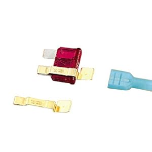
http://www.google.com/imgres?imgurl=...1t:429,r:1,s:0 is that an example of a fuse tap line?
http://www.google.com/imgres?imgurl=...1t:429,r:1,s:0 is that an example of a fuse tap line?
4th Gear Member
Joined: Dec 2010
Posts: 1,597
From: Gallifrey
Kinda. Thinking a bit more basic, you can get a bag of the basic ones for a buck I think. Just yank the existing fuse, put this on over actual pin of the fuse that would cause the fuse to blow should an overdraw/short occur (usually right-side relative), but again easily verified with a multi-meter with the fuse pulled:
Last edited by wayne613; Jan 29, 2011 at 01:51 AM.