

 Oct 8, 2015, 01:08 PM
Last edit by: IB Advertising
See related guides and technical advice from our community experts:
Browse all: Brake Guides
- Ford Mustang V6 and GT 1996 to 2014: How to Replace Brake Line
Step by step instructions for do-it-yourself repairs
Browse all: Brake Guides

Attaching a brake line bracket to frame?

Thread Starter
3rd Gear Member
Joined: Feb 2007
Posts: 880
From: Mansfield, Texas
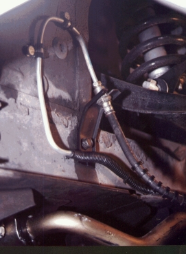
Here is a picture from MustangSteve's GRANADA swap page. I'm using the CSRP swap, so it's nearly the same, at least for this question.
http://www.mustangsteve.com/HoseRoutingAlternate.jpg
There is a bracket right in the center of this picture (driver's side) that connects the steel brake line to the rubber brake line.
I have the bracket to do this, as well as the "extender" hard brake line. I guess I would drill a hole into the frame rail and attach this bracket to it? There is also a small "tab" at the end of the bracket. It somehow slips into ... something...
Any advice?
Thanks,

5th Gear Member
Joined: Sep 2006
Posts: 3,302
From: Northernish Eastish Central Texas
Hey Steven,
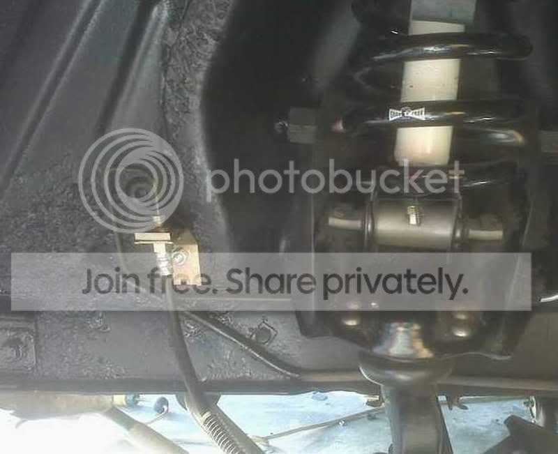
Just take the bracket and locate it approximately like the attach point shown in Steve's pic. Then drill a hole in the frame and attach. you can drill a smaller hole farther back for the tab to sit in, that will keep it from twisting. Here's how I did mine years ago. I thought it put the hose in a better position. Now, I don't think it really matters.
Just take the bracket and locate it approximately like the attach point shown in Steve's pic. Then drill a hole in the frame and attach. you can drill a smaller hole farther back for the tab to sit in, that will keep it from twisting. Here's how I did mine years ago. I thought it put the hose in a better position. Now, I don't think it really matters.
5th Gear Member
Joined: Sep 2006
Posts: 3,302
From: Northernish Eastish Central Texas
Or, for about 10 bucks, you can buy tabs that you can rivet to the frame to hold the line.
From Speedway Motors
http://www.speedwaymotors.com/Remova...Tabs,4854.html

From Speedway Motors
http://www.speedwaymotors.com/Remova...Tabs,4854.html
2nd Gear Member
Joined: Dec 2008
Posts: 386
From: Benicia, Ca
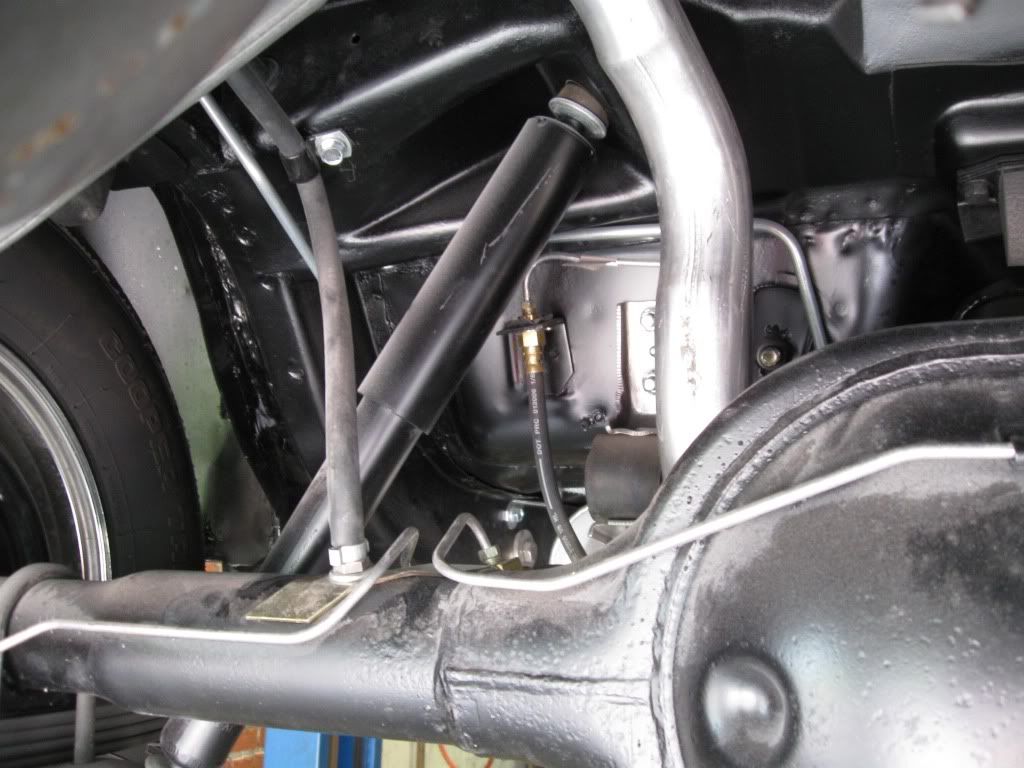
I tried the original location but it made the hose tight when it was turned fully. I bought a straight section of pre made tubing (24 inch if I remember right) and a coupling to join it to the existing line. I drilled new holes for the the bracket and mounted in on the front side. I bent the lines to follow the frame rail.
There pictures of my CSRP swap on my site: http://chris66dad.tripod.com/id12.html
There pictures of my CSRP swap on my site: http://chris66dad.tripod.com/id12.html
Last edited by chris66dad; Jan 22, 2010 at 08:27 PM.

5th Gear Member
Joined: Jan 2006
Posts: 3,946
From: Colorado
I see how the brake line are routed in both the pictures above and wonder how you get all the air out of the line when the hard line is routed up and then down and forms a loop. It seems that air would get trapped in the hard line at that loop. You won't find factory line routed like that. A factory line will always always go lower and lower as you get closer to the wheel and the connection to the flex line will be horizontal not verticle. Any trouble getting the brakes bled on those cars?

5th Gear Member
Joined: Sep 2006
Posts: 3,302
From: Northernish Eastish Central Texas
I see how the brake line are routed in both the pictures above and wonder how you get all the air out of the line when the hard line is routed up and then down and forms a loop. It seems that air would get trapped in the hard line at that loop. You won't find factory line routed like that. A factory line will always always go lower and lower as you get closer to the wheel and the connection to the flex line will be horizontal not verticle. Any trouble getting the brakes bled on those cars?
2nd Gear Member
Joined: Dec 2005
Posts: 229
From:
I see how the brake line are routed in both the pictures above and wonder how you get all the air out of the line when the hard line is routed up and then down and forms a loop. It seems that air would get trapped in the hard line at that loop. You won't find factory line routed like that. A factory line will always always go lower and lower as you get closer to the wheel and the connection to the flex line will be horizontal not verticle. Any trouble getting the brakes bled on those cars?
Thread Starter
3rd Gear Member
Joined: Feb 2007
Posts: 880
From: Mansfield, Texas
Thanks JamesW and others. Got the lines up there to visualize how it would work and it looks good.
BTW, surprised you remembered me James, it's been probably 2 years, lol. Good to see ya
BTW, surprised you remembered me James, it's been probably 2 years, lol. Good to see ya