'67 Mustang Engine Swap Question

 10-01-2008, 06:36 PM
#12
6th Gear Member
Join Date: Feb 2007
Location: state of confusion
Posts: 7,635
Plan on doing quite a bit of structural reinforcement regardless of how much or how little trimming you end up doing just to get that beast of an engine to physically fit. You'll be adding a good bit of weight and probably doubling the torque reactions. That little front crossmember wasn't anything to write home about to begin with, and that was when it was brand-new 40 years ago. You need good, solid, straight load paths that don't just stop in the middle of nowhere (mid-panel = wrong answer).
Norm
Norm
Last edited by Norm Peterson; 10-01-2008 at 06:47 PM.
10-01-2008, 06:43 PM
#13
Thread Starter

Join Date: Oct 2008
Location: WA
Posts: 7
Oh yeah. I plan to reinforce the frame quite a bit. Swapping over suspension and most def the axles.
Besides them being original, they probably can't hold up to the power.
I figured i'll have to do quite a bit of custom fabrication to make it work good.
Besides them being original, they probably can't hold up to the power.
I figured i'll have to do quite a bit of custom fabrication to make it work good.
10-01-2008, 06:51 PM
#14
6th Gear Member
Join Date: Feb 2007
Location: state of confusion
Posts: 7,635
I did manage to sneak in a little edit after your last post. It's important enough that I get across what I'm thinking here (I do structural analysis stuff involving piping for a living).
Norm
Norm
10-01-2008, 07:08 PM
#16
4th Gear Member
Join Date: Sep 2008
Location: Connecticut
Posts: 1,839
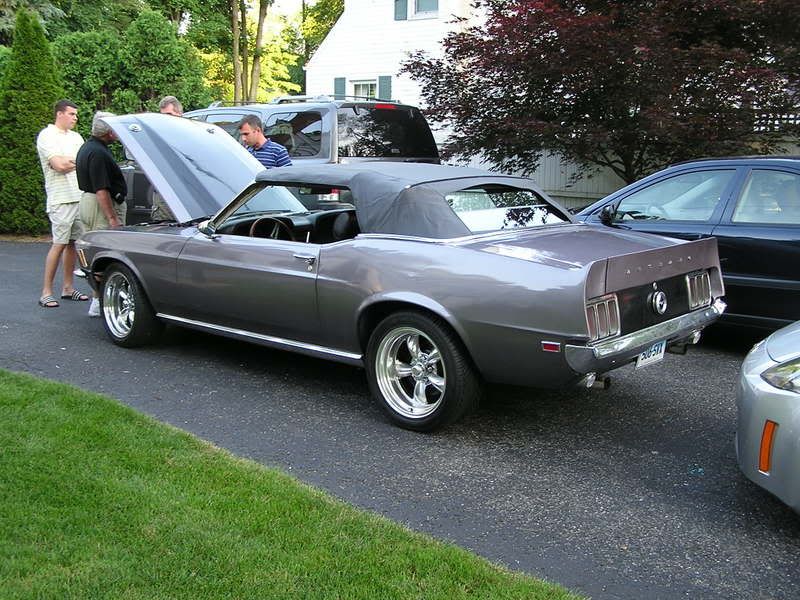
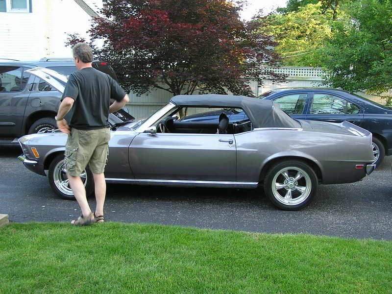
Here's the picture I promised of the 460 in my 1970 convertible:
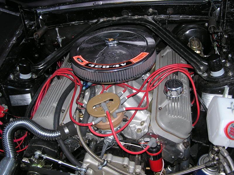
The shock towers are clearanced and reinforced. Subframe connectors were welded in to connect the front and rear subframes. The crossmember, radiator core support, front and rear inner fenders, and strut rod frames were all replaced with beefier pieces. I made the headers by purchasing a set for a 1971 Mustang with a 429 and a bunch of 1 3/4" mandrel bent tubes. A chop saw, welder, a couple of days work, and a trip to the ceramic coater and I was good to go.
The shock towers are clearanced and reinforced. Subframe connectors were welded in to connect the front and rear subframes. The crossmember, radiator core support, front and rear inner fenders, and strut rod frames were all replaced with beefier pieces. I made the headers by purchasing a set for a 1971 Mustang with a 429 and a bunch of 1 3/4" mandrel bent tubes. A chop saw, welder, a couple of days work, and a trip to the ceramic coater and I was good to go.
Last edited by fakesnakes; 10-01-2008 at 07:10 PM.

 10-01-2008, 07:33 PM
#19
6th Gear Member
Join Date: Feb 2007
Location: state of confusion
Posts: 7,635
Prozon - (slow typing catches up with me again) - the framework in the engine compartment (such as it is) does not continue in an unbroken/unkinked path rearward. It connects, sort of, to the sills throught torque boxes, which is a better solution than nothing at all but involves abrupt changes in the stresses.
Near as I can tell, where the tops of the upper inner fender sheetmetal attach at to the toeboard up to the cowl is sheetmetal at 90� to sheetmetal (flanged and spotwelded), with the mostly vertical engine bay metal crossing the mostly horizontal bottom of the vent plenum. In order to get loads to go into the engine bay sheetmetal (because it's better than forcing the lower rectangular portions to do all the work), you have to give it a good way out at the firewall, and I'm not seeing that to be the case at least at your power level.
When forces have to "bend around sharp corners" because that's where the structure goes, they develop stress concentrations and concentrated metal deflections (translation: breeding ground for cracks and always a loss of chassis stiffness). What's OK for maybe 300 HP (flywheel net) can't be counted on at the 600 level, long term. I'm a little cautious here - I've had a different make small-block powered car crack its frame structure where two structural members connected, and I've never been into doing drag racing starts and burnouts.
Norm
Last edited by Norm Peterson; 10-01-2008 at 07:36 PM.

Thread
Thread Starter
Forum
Replies
Last Post
tj@steeda
Steeda Autosports
0
10-01-2015 09:11 PM